
User Manual
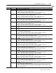
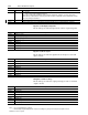
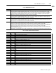
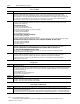
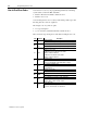
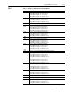
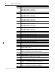
Table Of Contents
- 1771-6.5.88, Plastic Molding Module Reference Manual
- Summary of Changes
- Table of Contents
- Preface
- 1 - Abbreviated Command and Status Blocks
- Chapter Contents
- CLC - Clamp and Eject ERC Values Block
- CPC - Clamp Close Profile Block
- DYC - Dynamic Command Block
- EAC - Ejector Advance Configuration Block
- EPC - Ejector Profile Block
- ERC - Ejector Retract Configuration Block
- FCC - First Clamp Close Configuration Block
- FOC - First Clamp Open Configuration Block
- HDC - Hold Configuration Block
- HPC - Pack/Hold Profile Block
- INC - Injection Configuration Block
- IPC - Injection Profile Block
- JGC - Jog Configuration Block
- LPC - Clamp Low Pressure Close Configuration Block
- MCC - Module Configuration Command Block
- OPC - Clamp Open Profile Block
- OSC - Clamp Open Slow Configuration Block
- PKC - Pack Configuration Block
- PLC - Plastication Configuration Block
- PPC - Plastication Profile Block
- PRC - Pre-decompression Configuration Block
- PSC - Post- decompression Configuration Block
- PTC - Process Trace Configuration Block
- RLC - Inject ERC Values Block
- SCC - Second Clamp Close Configuration Block
- SOC - Second Clamp Open Configuration Block
- TCC - Third Clamp Close Configuration Block
- TOC - Third Clamp Open Configuration Block
- CLS - Clamp and Eject ERC Values Status Block
- CPS - Clamp Close Profiles Status Block
- EPS - Ejector Profile Status Block
- HPS - Pack/Hold Profile Status Block
- IPS - Injection Profile Status Block
- OPS - Clamp Open Profiles Status Block
- PPS - Plastication Profile Status Block
- PTS - Process Trace Status Block
- RLS - Inject ERC Values Status Block
- SYS - System Status Block
- 2 - Command Word/Bit Descriptions
- Alphabetical List of Command Blocks and Block ID Codes
- List of Data Words
- Engineering Units
- Data Blocks Require I/O Configuration
- Data Blocks for System Control
- Data Blocks for Controlling Ram (Screw) Position
- Data Blocks for Controlling Clamp Position
- Data Blocks for Controlling Ejector Position
- Sensors Required
- CLC CLC - Clamp and Eject ERC Values Block
- CPC - Clamp Close Profile Block
- DYC DYC - Dynamic Command Block
- EAC - Ejector Advance Configuration Block
- EPC - Ejector Profile Block
- ERC - Ejector Retract Configuration Block
- FCC - First Clamp Close Configuration Block
- FOC - First Clamp Open Configuration Block
- HDC - Hold Configuration Block
- HPC - Pack/Hold Profile Block
- INC - Injection Configuration Block
- IPC - Injection Profile Block
- JGC - Jog Configuration Block
- LPC - Clamp Low Pressure Close Configuration Block
- MCC - Module Configuration Command Block
- OPC - Clamp Open Profile Block
- OSC - Clamp Open Slow Configuration Block
- PKC - Pack Configuration Block
- PLC Plastication Configuration Command Block (PLC)
- PPC - Plastication Profile Block
- PRC - Pre-decompression Configuration Block
- PSC - Post-decompression Configuration Block
- PTC - Process Trace Configuration Block
- RLC - Inject ERC Values Block
- SCC - Second Clamp Close Configuration Block
- SOC - Second Clamp Open Configuration Block
- TCC - Third Clamp Close Configuration Block
- TOC - Third Clamp Open Configuration Block
- 3 - Word/Bit Descriptions
- List of Status Blocks and Block ID Codes
- List of Data Words
- Data Blocks Require I/O Configuration
- Engineering Units
- Status Block for Reporting System Status
- Status Blocks for Reporting Ram (Screw) Position
- Status Blocks for Reporting Clamp Position
- Status Blocks for Reporting Ejector Position
- CLS - Clamp and Eject ERC Values Status Block
- CPS - Clamp Close Profiles Status Block
- EPS - Ejector Profile Status Block
- HPS - Pack/Hold Profile Status Block
- IPS ú Injection Profile Status Block
- OPS - Clamp Open Profiles Status Block
- PPS - Plastication Profile Status Block
- PTS - Process Trace Status Block
- RLS - Inject ERC Values Status Block
- SYS - System Status Block
- 4 - Programming Error Codes
- 5 - Module Specifications
- 6 - Calibration Instructions
- A - Single transfer for Reporting Ejector Status
- Back cover

3–48 Status Word/Bit Descriptions
Publication
1771-6.5.88 – July 1997
Notes: 1. For [ ] engineering units, see page 3.
2. When using the Inject/Clamp/Eject mode, all pressure readings are system pressure at input 2, except where noted.
Process Times
Word Description
SYS57 Accumulated Tonnage Time [21]
If bit patterns in MCC02 and MCC03 indicate that the module is connected to a clamp pressure transducer, the module:
S
clears this word and starts tonnage watchdog timer when it completes Clamp LPC Profile and sets its outputs to LPC33 - 40
S
stops timer when it sets master status bit SYS03-B02 and reports accumulated value of timer (99.99 seconds max) in this word
S
sets master status bit SYS04-B15 when this value equals or exceeds LPC07. A zero entry in LPC07 inhibits SYS04-B15.
The module also resets this word to zero when it detects an F-to-T transition of DYC03-B00.
SYS58 Accumulated Cure Time [22]
If bit patterns in MCC02 and MCC03 indicate that the module is connected to a ram (screw) position transducer, the module:
At completion of the Hold Profile:
S
starts an internal cure timer
S
starts an internal cure timer
S
sets master status bit SYS03-B03
S
reports the accumulated time in this word
When the value in this word equals the cure timer preset (HPC6:
When
the
value
in
this
word
equals
the
cure
timer
reset
(HPC6:
S
resets master status bit SYS03-B03
S
sets master status bit SYS03-B05
S
stops accumulating time in this word
When it receives an F-to-T transition of DYC03-B01
Wh
en
it
rece
i
ves an
F
-
t
o-
T
t
rans
iti
on o
f
DYC03
-
B01
S
resets master status bit SYS03-B03
S
resets master status bit SYS03-B05 resets this word to zero
If bit patterns in MCC02 and MCC03 indicate that the module is connected to both a ram (screw) position transducer and a clamp
position transducer the module also (when it receives an F to T transition of DYC02 B00 B01 B02 or B03):
position transducer, the module also (when it receives an F-to-T transition of DYC02-B00, -B01, -B02, or -B03):
S
resets master status bit SYS03-B03
S
resets master status bit SYS03-B05
S
resets this word to zero
SYS59 Accumulated Mold Open Dwell Time [21]
SYS59
Accumulated
Mold
Oen
Dwell
Time
[21]
If bit patterns in MCC02 and MCC03 indicate that the module is connected to a clamp position transducer, the module:
reports the accumulated value of its internal Mold Open Dwell timer (maximum 99 99 seconds) in this word
S
reports the accumulated value of its internal Mold Open Dwell timer (maximum 99.99 seconds) in this word.
S
sets master status bit SYS03
-
B09 when the timer is timing
S
sets master status bit SYS03-B09 when the timer is timing.
S
stops the timer
,
resets SYS03-B09
,
and resets this word to zero upon receipt of an
y
action execution command bit
S
sto s
the
timer
,
resets
SYS03
-
B09
,
and
resets
this
word
to
zero
uon
recei t
of
any
action
execution
command
bit
except DYC02-B14 (execute ejector profile).
SYS60 Accumulated Cycle Time [22]
If bit patterns in MCC02 and MCC03 indicate that the module is connected to a clamp position transducer, the module:
S
resets this word to zero and starts an internal cycle timer when it detects an F-to-T transition of DYC02-B00
S
stops this timer when it sets master status bit SYS03-B11 and reports the accumulated value of the timer (maximum
of 999.9 seconds) in this word
Diagnostics
Word Description
SYS61 Programming Error Block
Module reports in the lower byte of this word a bit pattern copy of the block id associated with the command block that contained the
error referred to in SYS62. The priority order to be used by the module when reporting programming error codes will be as follows:
S
any MCC programming error
S
any DYC programming error
S
any programming error associated with DYC61
S
any other current programming error
SYS62 Programming Error Code
SYS63 Module Series/Revision
Upper byte - The module reports its firmware series in ASCII.
Lower byte - The module reports its firmware revision in ASCII.
New Status Confirmation
Word Description
SYS64 New data counter. The module sets this counter to zero on power start-up or above 9999, and increments this counter when it
sends a new SYS to its internal TIC chip.
Use this value to indicate that a most recent BTR of SYS is old data (last SYS64 equals new SYS64) or new data (last SYS64 is less
than new SYS64). You may also monitor the value to determine if you are missing any data (last SYS + 1 is less than new SYS64).