
User Manual
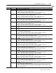
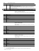
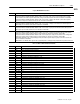
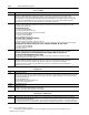
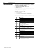
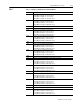
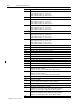
Table Of Contents
- 1771-6.5.88, Plastic Molding Module Reference Manual
- Summary of Changes
- Table of Contents
- Preface
- 1 - Abbreviated Command and Status Blocks
- Chapter Contents
- CLC - Clamp and Eject ERC Values Block
- CPC - Clamp Close Profile Block
- DYC - Dynamic Command Block
- EAC - Ejector Advance Configuration Block
- EPC - Ejector Profile Block
- ERC - Ejector Retract Configuration Block
- FCC - First Clamp Close Configuration Block
- FOC - First Clamp Open Configuration Block
- HDC - Hold Configuration Block
- HPC - Pack/Hold Profile Block
- INC - Injection Configuration Block
- IPC - Injection Profile Block
- JGC - Jog Configuration Block
- LPC - Clamp Low Pressure Close Configuration Block
- MCC - Module Configuration Command Block
- OPC - Clamp Open Profile Block
- OSC - Clamp Open Slow Configuration Block
- PKC - Pack Configuration Block
- PLC - Plastication Configuration Block
- PPC - Plastication Profile Block
- PRC - Pre-decompression Configuration Block
- PSC - Post- decompression Configuration Block
- PTC - Process Trace Configuration Block
- RLC - Inject ERC Values Block
- SCC - Second Clamp Close Configuration Block
- SOC - Second Clamp Open Configuration Block
- TCC - Third Clamp Close Configuration Block
- TOC - Third Clamp Open Configuration Block
- CLS - Clamp and Eject ERC Values Status Block
- CPS - Clamp Close Profiles Status Block
- EPS - Ejector Profile Status Block
- HPS - Pack/Hold Profile Status Block
- IPS - Injection Profile Status Block
- OPS - Clamp Open Profiles Status Block
- PPS - Plastication Profile Status Block
- PTS - Process Trace Status Block
- RLS - Inject ERC Values Status Block
- SYS - System Status Block
- 2 - Command Word/Bit Descriptions
- Alphabetical List of Command Blocks and Block ID Codes
- List of Data Words
- Engineering Units
- Data Blocks Require I/O Configuration
- Data Blocks for System Control
- Data Blocks for Controlling Ram (Screw) Position
- Data Blocks for Controlling Clamp Position
- Data Blocks for Controlling Ejector Position
- Sensors Required
- CLC CLC - Clamp and Eject ERC Values Block
- CPC - Clamp Close Profile Block
- DYC DYC - Dynamic Command Block
- EAC - Ejector Advance Configuration Block
- EPC - Ejector Profile Block
- ERC - Ejector Retract Configuration Block
- FCC - First Clamp Close Configuration Block
- FOC - First Clamp Open Configuration Block
- HDC - Hold Configuration Block
- HPC - Pack/Hold Profile Block
- INC - Injection Configuration Block
- IPC - Injection Profile Block
- JGC - Jog Configuration Block
- LPC - Clamp Low Pressure Close Configuration Block
- MCC - Module Configuration Command Block
- OPC - Clamp Open Profile Block
- OSC - Clamp Open Slow Configuration Block
- PKC - Pack Configuration Block
- PLC Plastication Configuration Command Block (PLC)
- PPC - Plastication Profile Block
- PRC - Pre-decompression Configuration Block
- PSC - Post-decompression Configuration Block
- PTC - Process Trace Configuration Block
- RLC - Inject ERC Values Block
- SCC - Second Clamp Close Configuration Block
- SOC - Second Clamp Open Configuration Block
- TCC - Third Clamp Close Configuration Block
- TOC - Third Clamp Open Configuration Block
- 3 - Word/Bit Descriptions
- List of Status Blocks and Block ID Codes
- List of Data Words
- Data Blocks Require I/O Configuration
- Engineering Units
- Status Block for Reporting System Status
- Status Blocks for Reporting Ram (Screw) Position
- Status Blocks for Reporting Clamp Position
- Status Blocks for Reporting Ejector Position
- CLS - Clamp and Eject ERC Values Status Block
- CPS - Clamp Close Profiles Status Block
- EPS - Ejector Profile Status Block
- HPS - Pack/Hold Profile Status Block
- IPS ú Injection Profile Status Block
- OPS - Clamp Open Profiles Status Block
- PPS - Plastication Profile Status Block
- PTS - Process Trace Status Block
- RLS - Inject ERC Values Status Block
- SYS - System Status Block
- 4 - Programming Error Codes
- 5 - Module Specifications
- 6 - Calibration Instructions
- A - Single transfer for Reporting Ejector Status
- Back cover

3–47Status Word/Bit Descriptions
Publication
1771-6.5.88 – July 1997
SYS
Cycle Maximum Pressures
Word Description
SYS49 Maximum Ram (Screw) Pressure During Last Cycle [01]
If bit patterns in MCC02 and MCC03 indicate that the module is connected to a ram (screw) pressure transducer but
not
a clamp
position transducer, the module reports the highest ram (screw) pressure it detected since the last F-to-T transition of DYC02-B04.
If bit patterns in MCC02 and MCC03 indicate that the module is connected to a clamp position transducer, the module reports the
highest ram (screw) pressure it detected since the last F-to-T transition of DYC02-B00.
SYS50 Maximum Clamp Pressure During Last Cycle [02]
If bit patterns in MCC02 and MCC03 indicate that the module is connected to a clamp pressure transducer, the module reports the
highest clamp pressure it detected since last F-to-T transition of DYC02-B00.
SYS51 Maximum Ejector Pressure During Last Cycle [03]
If bit patterns in MCC02 and MCC03 indicate that the module is connected to a ejector pressure transducer, the module reports the
highest ejector pressure it detected since last F-to-T transition of DYC02-B00.
SYS52 Maximum Cavity (or System) Pressure During Last Cycle [04]
If bit patterns in MCC02 and MCC03 indicate that the module is connected to a cavity pressure transducer but
not
a clamp position
transducer, the module reports the highest cavity pressure it detected since the last F-to-T transition of DYC02-B04.
If bit patterns in MCC02 and MCC03 indicate that the module is connected to both a cavity pressure transducer and a clamp position
transducer, the module reports the highest cavity pressure it detected since the last F-to-T transition of DYC02-B00.
If MCC02-B03, B04, B05 are all set, (inject/clamp/eject mode) the module reports the highest system pressure it detected since the
last F-to-T transition of DYC02-B00.
If MCC02-B03 is set with B04, B05 in opposite states (inject/clamp mode or clamp/eject mode) module will not report data in this word
Process Trace Data Collection Status
Word Bit Description
SYS53 Process Trace status
B00 Process Trace data collection in progress.
B01 Process Trace data collection complete.
B02 - B15 Open
SYS54 Process Trace data collection in progress
B00 The module is collecting trace data points 1 to 50.
B01 The module is collecting trace data points 51 to 100.
B02 The module is collecting trace data points 101 to 150.
B03 The module is collecting trace data points 151 to 200.
B04 The module is collecting trace data points 201 to 250.
B05 The module is collecting trace data points 251 to 300.
B06 The module is collecting trace data points 301 to 350.
B07 The module is collecting trace data points 351 to 400.
B08 - B15 Open
SYS55 Process Trace data collection done
B00 The module has collected trace data points 1 to 50.
B01 The module has collected trace data points 51 to 100.
B02 The module has collected trace data points 101 to 150.
B03 The module has collected trace data points 151 to 200.
B04 The module has collected trace data points 201 to 250.
B05 The module has collected trace data points 251 to 300.
B06 The module has collected trace data points 301 to 350.
B07 The module has collected trace data points 351 to 400.
B08 - B15 Open
SYS56 Open