
User Manual
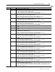
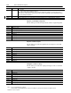
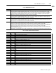
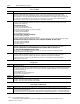
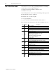
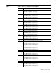
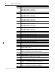
Table Of Contents
- 1771-6.5.88, Plastic Molding Module Reference Manual
- Summary of Changes
- Table of Contents
- Preface
- 1 - Abbreviated Command and Status Blocks
- Chapter Contents
- CLC - Clamp and Eject ERC Values Block
- CPC - Clamp Close Profile Block
- DYC - Dynamic Command Block
- EAC - Ejector Advance Configuration Block
- EPC - Ejector Profile Block
- ERC - Ejector Retract Configuration Block
- FCC - First Clamp Close Configuration Block
- FOC - First Clamp Open Configuration Block
- HDC - Hold Configuration Block
- HPC - Pack/Hold Profile Block
- INC - Injection Configuration Block
- IPC - Injection Profile Block
- JGC - Jog Configuration Block
- LPC - Clamp Low Pressure Close Configuration Block
- MCC - Module Configuration Command Block
- OPC - Clamp Open Profile Block
- OSC - Clamp Open Slow Configuration Block
- PKC - Pack Configuration Block
- PLC - Plastication Configuration Block
- PPC - Plastication Profile Block
- PRC - Pre-decompression Configuration Block
- PSC - Post- decompression Configuration Block
- PTC - Process Trace Configuration Block
- RLC - Inject ERC Values Block
- SCC - Second Clamp Close Configuration Block
- SOC - Second Clamp Open Configuration Block
- TCC - Third Clamp Close Configuration Block
- TOC - Third Clamp Open Configuration Block
- CLS - Clamp and Eject ERC Values Status Block
- CPS - Clamp Close Profiles Status Block
- EPS - Ejector Profile Status Block
- HPS - Pack/Hold Profile Status Block
- IPS - Injection Profile Status Block
- OPS - Clamp Open Profiles Status Block
- PPS - Plastication Profile Status Block
- PTS - Process Trace Status Block
- RLS - Inject ERC Values Status Block
- SYS - System Status Block
- 2 - Command Word/Bit Descriptions
- Alphabetical List of Command Blocks and Block ID Codes
- List of Data Words
- Engineering Units
- Data Blocks Require I/O Configuration
- Data Blocks for System Control
- Data Blocks for Controlling Ram (Screw) Position
- Data Blocks for Controlling Clamp Position
- Data Blocks for Controlling Ejector Position
- Sensors Required
- CLC CLC - Clamp and Eject ERC Values Block
- CPC - Clamp Close Profile Block
- DYC DYC - Dynamic Command Block
- EAC - Ejector Advance Configuration Block
- EPC - Ejector Profile Block
- ERC - Ejector Retract Configuration Block
- FCC - First Clamp Close Configuration Block
- FOC - First Clamp Open Configuration Block
- HDC - Hold Configuration Block
- HPC - Pack/Hold Profile Block
- INC - Injection Configuration Block
- IPC - Injection Profile Block
- JGC - Jog Configuration Block
- LPC - Clamp Low Pressure Close Configuration Block
- MCC - Module Configuration Command Block
- OPC - Clamp Open Profile Block
- OSC - Clamp Open Slow Configuration Block
- PKC - Pack Configuration Block
- PLC Plastication Configuration Command Block (PLC)
- PPC - Plastication Profile Block
- PRC - Pre-decompression Configuration Block
- PSC - Post-decompression Configuration Block
- PTC - Process Trace Configuration Block
- RLC - Inject ERC Values Block
- SCC - Second Clamp Close Configuration Block
- SOC - Second Clamp Open Configuration Block
- TCC - Third Clamp Close Configuration Block
- TOC - Third Clamp Open Configuration Block
- 3 - Word/Bit Descriptions
- List of Status Blocks and Block ID Codes
- List of Data Words
- Data Blocks Require I/O Configuration
- Engineering Units
- Status Block for Reporting System Status
- Status Blocks for Reporting Ram (Screw) Position
- Status Blocks for Reporting Clamp Position
- Status Blocks for Reporting Ejector Position
- CLS - Clamp and Eject ERC Values Status Block
- CPS - Clamp Close Profiles Status Block
- EPS - Ejector Profile Status Block
- HPS - Pack/Hold Profile Status Block
- IPS ú Injection Profile Status Block
- OPS - Clamp Open Profiles Status Block
- PPS - Plastication Profile Status Block
- PTS - Process Trace Status Block
- RLS - Inject ERC Values Status Block
- SYS - System Status Block
- 4 - Programming Error Codes
- 5 - Module Specifications
- 6 - Calibration Instructions
- A - Single transfer for Reporting Ejector Status
- Back cover

3–46 Status Word/Bit Descriptions
Publication
1771-6.5.88 – July 1997
Notes: 1. For [ ] engineering units, see page 3.
2. When using the Inject/Clamp/Eject mode, all pressure readings are system pressure at input 2, except where noted.
Word DescriptionBit
B15 = 0 Normal
= 1 End of Ejector Retract Set-Output in Progress
The module sets this bit when holding its outputs to ERC33 - ERC40 after completion of an ejector retract stroke.
The module resets this bit when it receives any new action execution command bit, or when commanded to continue
the ejector profile by DYC03-B15 = 1.
SYS23 Double command error. You can determine from DYC01 which bits were set or downloaded at the same time.
SYS24 Double command error. You can determine from DYC02 which bits were set or downloaded at the same time.
Input Level In Engineering Units
The module reports real-time input levels scaled to engineering units.
Word Description
SYS25 Input #1 [11] or [15]
SYS26 Input #2 [01] or [02] or [03]
SYS27 Input #3 [13] or [25]
SYS28 Input #4 [02] or [04]
SYS29 Input #5 [15]
SYS30 Input #6 [03]
SYS31 Input #7 [25]
SYS32 Input #8 [04]
Input Level, Raw Signal
The module reports real-time signal levels at the input to each A/D
input converter.
Word Description
SYS33 Input #1 [24]
SYS34 Input #2 [24]
SYS35 Input #3 [24]
SYS36 Input #4 [24]
SYS37 Input #5 [24]
SYS38 Input #6 [24]
SYS39 Input #7 [24]
SYS40 Input #8 [24]
Output Level in Percentage
The module reports real-time output percentage it sends to each D/A
output converter.
Word Description
SYS41 Output #1 [19]
SYS42 Output #2 [19]
SYS43 Output #3 [19]
SYS44 Output #4 [19]
SYS45 Output #5 [19]
SYS46 Output #6 [19]
SYS47 Output #7 [19]
SYS48 Output #8 [19]