
User Manual
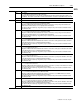

Table Of Contents
- 1771-6.5.88, Plastic Molding Module Reference Manual
- Summary of Changes
- Table of Contents
- Preface
- 1 - Abbreviated Command and Status Blocks
- Chapter Contents
- CLC - Clamp and Eject ERC Values Block
- CPC - Clamp Close Profile Block
- DYC - Dynamic Command Block
- EAC - Ejector Advance Configuration Block
- EPC - Ejector Profile Block
- ERC - Ejector Retract Configuration Block
- FCC - First Clamp Close Configuration Block
- FOC - First Clamp Open Configuration Block
- HDC - Hold Configuration Block
- HPC - Pack/Hold Profile Block
- INC - Injection Configuration Block
- IPC - Injection Profile Block
- JGC - Jog Configuration Block
- LPC - Clamp Low Pressure Close Configuration Block
- MCC - Module Configuration Command Block
- OPC - Clamp Open Profile Block
- OSC - Clamp Open Slow Configuration Block
- PKC - Pack Configuration Block
- PLC - Plastication Configuration Block
- PPC - Plastication Profile Block
- PRC - Pre-decompression Configuration Block
- PSC - Post- decompression Configuration Block
- PTC - Process Trace Configuration Block
- RLC - Inject ERC Values Block
- SCC - Second Clamp Close Configuration Block
- SOC - Second Clamp Open Configuration Block
- TCC - Third Clamp Close Configuration Block
- TOC - Third Clamp Open Configuration Block
- CLS - Clamp and Eject ERC Values Status Block
- CPS - Clamp Close Profiles Status Block
- EPS - Ejector Profile Status Block
- HPS - Pack/Hold Profile Status Block
- IPS - Injection Profile Status Block
- OPS - Clamp Open Profiles Status Block
- PPS - Plastication Profile Status Block
- PTS - Process Trace Status Block
- RLS - Inject ERC Values Status Block
- SYS - System Status Block
- 2 - Command Word/Bit Descriptions
- Alphabetical List of Command Blocks and Block ID Codes
- List of Data Words
- Engineering Units
- Data Blocks Require I/O Configuration
- Data Blocks for System Control
- Data Blocks for Controlling Ram (Screw) Position
- Data Blocks for Controlling Clamp Position
- Data Blocks for Controlling Ejector Position
- Sensors Required
- CLC CLC - Clamp and Eject ERC Values Block
- CPC - Clamp Close Profile Block
- DYC DYC - Dynamic Command Block
- EAC - Ejector Advance Configuration Block
- EPC - Ejector Profile Block
- ERC - Ejector Retract Configuration Block
- FCC - First Clamp Close Configuration Block
- FOC - First Clamp Open Configuration Block
- HDC - Hold Configuration Block
- HPC - Pack/Hold Profile Block
- INC - Injection Configuration Block
- IPC - Injection Profile Block
- JGC - Jog Configuration Block
- LPC - Clamp Low Pressure Close Configuration Block
- MCC - Module Configuration Command Block
- OPC - Clamp Open Profile Block
- OSC - Clamp Open Slow Configuration Block
- PKC - Pack Configuration Block
- PLC Plastication Configuration Command Block (PLC)
- PPC - Plastication Profile Block
- PRC - Pre-decompression Configuration Block
- PSC - Post-decompression Configuration Block
- PTC - Process Trace Configuration Block
- RLC - Inject ERC Values Block
- SCC - Second Clamp Close Configuration Block
- SOC - Second Clamp Open Configuration Block
- TCC - Third Clamp Close Configuration Block
- TOC - Third Clamp Open Configuration Block
- 3 - Word/Bit Descriptions
- List of Status Blocks and Block ID Codes
- List of Data Words
- Data Blocks Require I/O Configuration
- Engineering Units
- Status Block for Reporting System Status
- Status Blocks for Reporting Ram (Screw) Position
- Status Blocks for Reporting Clamp Position
- Status Blocks for Reporting Ejector Position
- CLS - Clamp and Eject ERC Values Status Block
- CPS - Clamp Close Profiles Status Block
- EPS - Ejector Profile Status Block
- HPS - Pack/Hold Profile Status Block
- IPS ú Injection Profile Status Block
- OPS - Clamp Open Profiles Status Block
- PPS - Plastication Profile Status Block
- PTS - Process Trace Status Block
- RLS - Inject ERC Values Status Block
- SYS - System Status Block
- 4 - Programming Error Codes
- 5 - Module Specifications
- 6 - Calibration Instructions
- A - Single transfer for Reporting Ejector Status
- Back cover

3–27Status Word/Bit Descriptions
Publication
1771-6.5.88 – July 1997
SYS
Word Bit Description
SYS03 Miscellaneous Status
B00 = 0 Normal
= 1 Clamp in Mold Protection Zone
If bit patterns in MCC02 and MCC03 indicate that the module is connected to a clamp position transducer, the module
sets this bit when clamp position is equal to or less than the Start Clamp Low Pressure Close position (CPC61).
B01 = 0 Normal
= 1 Mold Safe
If bit patterns in MCC02 and MCC03 indicate that the module is connected to a clamp position transducer, the module
sets this bit when clamp position is equal to or less than the Mold Safe position (CPC62).
B02 = 0 Normal
= 1 Tonnage Complete
If bit patterns in MCC02 and MCC03 indicate that the module is connected to a clamp pressure transducer, the module
latches this bit when both of the following are true:
S
clamp pressure equals or exceeds the Tonnage Pressure (CPC63).
S
clamp position equals or is less than the Mold Safe position (CPC62).
The module unlatches this bit when either of the following are true:
S
clamp pressure is less than the Tonnage Pressure (CPC63).
S
clamp position exceeds the Mold Safe position (CPC62).
B03 = 0 Normal
= 1 Cure Timer Timing
If bit patterns in MCC02 and MCC03 indicate that the module is connected to a ram (screw) position transducer, the
module sets this bit when the internal Cure Timer is timing and the accumulated Cure Time (SYS58) is less than the
Cure Timer preset (HPC61).
B04 = 0 Normal
= 1 Ram (Screw) Retracted
If bit patterns in MCC02 and MCC03 indicate that the module is connected to a ram (screw) position transducer, the
module sets this bit when ram (screw) position equals or exceeds the Full Retract position of Cushion + Shot Size +
Post-decompression (PPC61 + PPC62 + PSC05).
B05 = 0 Normal
= 1 Cure Time Complete
If bit patterns in MCC02 and MCC03 indicate that the module is connected to a ram (screw) position transducer, the
module sets this bit when the accumulated value of its internal Cure Timer (SYS58) equals the Cure Timer preset
(HPC61).
B06 = 0 Normal
= 1 Clamp in Open Slow Zone
If bit patterns in MCC02 and MCC03 indicate that the module is connected to a clamp position transducer, the module
sets this bit when clamp position equals or exceeds the Start Clamp Open Slow position (OPC61).
B07 = 0 Normal
= 1 Mold Open
If bit patterns in MCC02 and MCC03 indicate that the module is connected to a clamp position transducer, the module
sets this bit when clamp position equals or exceeds the Mold Open position (OPC62) with hysteresis of 0.05” (0.5mm).
B08 = 0 Normal
= 1 Ejector Profile stopped at End of Stroke.
If bit patterns in MCC02 and MCC03 indicate that the module is connected to a ejector position transducer, the module:
latches this bit if EPC03-B12 is SET and ejector position reaches any of the following:
S
EPC59 during Ejector Profile full-advance stroke
S
EPC23 during Ejector Profile tip-retract stroke
S
EPC29 during Ejector Profile tip-advance stroke
S
EPC60 during Ejector Profile full-retract stroke when the total advance strokes executed during the profile is less than
EPC64
does not latch this bit at completion of final full-retract stroke
unlatches this bit when any one of the following occur:
S
the module decodes a valid DYC having DYC03-B15 SET.
S
the module decodes a valid EPC having EPC03-B12 RESET.
S
Early termination of the Ejector Profile is forced by receipt of a new action execution command bit.