
User Manual

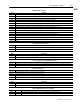
Table Of Contents
- 1771-6.5.88, Plastic Molding Module Reference Manual
- Summary of Changes
- Table of Contents
- Preface
- 1 - Abbreviated Command and Status Blocks
- Chapter Contents
- CLC - Clamp and Eject ERC Values Block
- CPC - Clamp Close Profile Block
- DYC - Dynamic Command Block
- EAC - Ejector Advance Configuration Block
- EPC - Ejector Profile Block
- ERC - Ejector Retract Configuration Block
- FCC - First Clamp Close Configuration Block
- FOC - First Clamp Open Configuration Block
- HDC - Hold Configuration Block
- HPC - Pack/Hold Profile Block
- INC - Injection Configuration Block
- IPC - Injection Profile Block
- JGC - Jog Configuration Block
- LPC - Clamp Low Pressure Close Configuration Block
- MCC - Module Configuration Command Block
- OPC - Clamp Open Profile Block
- OSC - Clamp Open Slow Configuration Block
- PKC - Pack Configuration Block
- PLC - Plastication Configuration Block
- PPC - Plastication Profile Block
- PRC - Pre-decompression Configuration Block
- PSC - Post- decompression Configuration Block
- PTC - Process Trace Configuration Block
- RLC - Inject ERC Values Block
- SCC - Second Clamp Close Configuration Block
- SOC - Second Clamp Open Configuration Block
- TCC - Third Clamp Close Configuration Block
- TOC - Third Clamp Open Configuration Block
- CLS - Clamp and Eject ERC Values Status Block
- CPS - Clamp Close Profiles Status Block
- EPS - Ejector Profile Status Block
- HPS - Pack/Hold Profile Status Block
- IPS - Injection Profile Status Block
- OPS - Clamp Open Profiles Status Block
- PPS - Plastication Profile Status Block
- PTS - Process Trace Status Block
- RLS - Inject ERC Values Status Block
- SYS - System Status Block
- 2 - Command Word/Bit Descriptions
- Alphabetical List of Command Blocks and Block ID Codes
- List of Data Words
- Engineering Units
- Data Blocks Require I/O Configuration
- Data Blocks for System Control
- Data Blocks for Controlling Ram (Screw) Position
- Data Blocks for Controlling Clamp Position
- Data Blocks for Controlling Ejector Position
- Sensors Required
- CLC CLC - Clamp and Eject ERC Values Block
- CPC - Clamp Close Profile Block
- DYC DYC - Dynamic Command Block
- EAC - Ejector Advance Configuration Block
- EPC - Ejector Profile Block
- ERC - Ejector Retract Configuration Block
- FCC - First Clamp Close Configuration Block
- FOC - First Clamp Open Configuration Block
- HDC - Hold Configuration Block
- HPC - Pack/Hold Profile Block
- INC - Injection Configuration Block
- IPC - Injection Profile Block
- JGC - Jog Configuration Block
- LPC - Clamp Low Pressure Close Configuration Block
- MCC - Module Configuration Command Block
- OPC - Clamp Open Profile Block
- OSC - Clamp Open Slow Configuration Block
- PKC - Pack Configuration Block
- PLC Plastication Configuration Command Block (PLC)
- PPC - Plastication Profile Block
- PRC - Pre-decompression Configuration Block
- PSC - Post-decompression Configuration Block
- PTC - Process Trace Configuration Block
- RLC - Inject ERC Values Block
- SCC - Second Clamp Close Configuration Block
- SOC - Second Clamp Open Configuration Block
- TCC - Third Clamp Close Configuration Block
- TOC - Third Clamp Open Configuration Block
- 3 - Word/Bit Descriptions
- List of Status Blocks and Block ID Codes
- List of Data Words
- Data Blocks Require I/O Configuration
- Engineering Units
- Status Block for Reporting System Status
- Status Blocks for Reporting Ram (Screw) Position
- Status Blocks for Reporting Clamp Position
- Status Blocks for Reporting Ejector Position
- CLS - Clamp and Eject ERC Values Status Block
- CPS - Clamp Close Profiles Status Block
- EPS - Ejector Profile Status Block
- HPS - Pack/Hold Profile Status Block
- IPS ú Injection Profile Status Block
- OPS - Clamp Open Profiles Status Block
- PPS - Plastication Profile Status Block
- PTS - Process Trace Status Block
- RLS - Inject ERC Values Status Block
- SYS - System Status Block
- 4 - Programming Error Codes
- 5 - Module Specifications
- 6 - Calibration Instructions
- A - Single transfer for Reporting Ejector Status
- Back cover

3–12 Status Word/Bit Descriptions
Publication
1771-6.5.88 – July 1997
Notes: 1. For [ ] engineering units, see page 3.
2. When using the Inject/Clamp/Eject mode, all pressure readings are system pressure at input 2, except where noted.
Word DescriptionBit
HPS08 CV Low Limit Alarms
For Pack Phase
The module latches each bit when executing the subject profile segment in closed loop, and drives its algorithm CV to
minimum (0%) in an attempt to control the profile setpoint.
The module unlatches each bit when it completes execution of the subject profile segment in open loop, or in closed
loop without driving its algorithm CV to minimum (0%).
When this bit
is latched ON:
algorithm CV
is minimum during:
B00 Pack Segment 1
B01 Pack Segment 2
B02 Pack Segment 3
B03 Pack Segment 4
B04 Pack Segment 5
B05-B07 Open
For Hold Phase
The module latches each bit when executing the subject profile segment in closed loop, and drives its algorithm CV to
minimum (0%) in an attempt to control the profile setpoint.
The module unlatches each bit when it completes execution of the subject profile segment in open loop, or in closed
loop without driving its algorithm CV to minimum (0%).
When this bit
is latched ON:
algorithm CV
is minimum during:
B08 Hold Segment 1
B09 Hold Segment 2
B10 Hold Segment 3
B11 Hold Segment 4
B12 Hold Segment 5
B13-B15 Open
Pack Profile Actuals
Word Description
HPS09 Actual Pack Segment 1 Cavity Pressure [04] Average cavity pressure during last Segment 1.
HPS10 Actual Pack Segment 1 Ram (Screw) Pressure [01] Average ram (screw) pressure during last Segment 1.
HPS11 Actual Pack End of Segment 1 Position [12] Ram (Screw) position at completion of last Segment 1.
HPS12 Actual Pack Segment 2 Cavity Pressure [04] Average cavity pressure during last Segment 2.
HPS13 Actual Pack Segment 2 Ram (Screw) Pressure [01] Average ram (screw) pressure during last Segment 2.
HPS14 Actual Pack End of Segment 2 Position [12] Ram (Screw) position at completion of last Segment 2.
HPS15 Actual Pack Segment 3 Cavity Pressure [04] Average cavity pressure during last Segment 3.
HPS16 Actual Pack Segment 3 Ram (Screw) Pressure [01] Average ram (screw) pressure during last Segment 3.
HPS17 Actual Pack End of Segment 3 Position [12] Ram (Screw) position at completion of last Segment 3.
HPS18 Actual Pack Segment 4 Cavity Pressure [04] Average cavity pressure during last Segment 4.
HPS19 Actual Pack Segment 4 Ram (Screw) Pressure [01] Average ram (screw) pressure during last Segment 4.
HPS20 Actual Pack End of Segment 4 Position [12] Ram (Screw) position at completion of last Segment 4.
HPS21 Actual
Pack Segment 5 Cavity Pressure [04] Average cavity pressure during last Segment 5.
HPS22 Actual Pack Segment 5 Ram (Screw) Pressure [01] Average ram (screw) pressure during last Segment 5.
HPS23 Actual Pack End of Segment 5 Position [12] Ram (Screw) position at completion of last Segment 5.
HPS24 - 25 Open