
User Manual
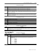
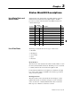
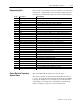
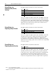
Table Of Contents
- 1771-6.5.88, Plastic Molding Module Reference Manual
- Summary of Changes
- Table of Contents
- Preface
- 1 - Abbreviated Command and Status Blocks
- Chapter Contents
- CLC - Clamp and Eject ERC Values Block
- CPC - Clamp Close Profile Block
- DYC - Dynamic Command Block
- EAC - Ejector Advance Configuration Block
- EPC - Ejector Profile Block
- ERC - Ejector Retract Configuration Block
- FCC - First Clamp Close Configuration Block
- FOC - First Clamp Open Configuration Block
- HDC - Hold Configuration Block
- HPC - Pack/Hold Profile Block
- INC - Injection Configuration Block
- IPC - Injection Profile Block
- JGC - Jog Configuration Block
- LPC - Clamp Low Pressure Close Configuration Block
- MCC - Module Configuration Command Block
- OPC - Clamp Open Profile Block
- OSC - Clamp Open Slow Configuration Block
- PKC - Pack Configuration Block
- PLC - Plastication Configuration Block
- PPC - Plastication Profile Block
- PRC - Pre-decompression Configuration Block
- PSC - Post- decompression Configuration Block
- PTC - Process Trace Configuration Block
- RLC - Inject ERC Values Block
- SCC - Second Clamp Close Configuration Block
- SOC - Second Clamp Open Configuration Block
- TCC - Third Clamp Close Configuration Block
- TOC - Third Clamp Open Configuration Block
- CLS - Clamp and Eject ERC Values Status Block
- CPS - Clamp Close Profiles Status Block
- EPS - Ejector Profile Status Block
- HPS - Pack/Hold Profile Status Block
- IPS - Injection Profile Status Block
- OPS - Clamp Open Profiles Status Block
- PPS - Plastication Profile Status Block
- PTS - Process Trace Status Block
- RLS - Inject ERC Values Status Block
- SYS - System Status Block
- 2 - Command Word/Bit Descriptions
- Alphabetical List of Command Blocks and Block ID Codes
- List of Data Words
- Engineering Units
- Data Blocks Require I/O Configuration
- Data Blocks for System Control
- Data Blocks for Controlling Ram (Screw) Position
- Data Blocks for Controlling Clamp Position
- Data Blocks for Controlling Ejector Position
- Sensors Required
- CLC CLC - Clamp and Eject ERC Values Block
- CPC - Clamp Close Profile Block
- DYC DYC - Dynamic Command Block
- EAC - Ejector Advance Configuration Block
- EPC - Ejector Profile Block
- ERC - Ejector Retract Configuration Block
- FCC - First Clamp Close Configuration Block
- FOC - First Clamp Open Configuration Block
- HDC - Hold Configuration Block
- HPC - Pack/Hold Profile Block
- INC - Injection Configuration Block
- IPC - Injection Profile Block
- JGC - Jog Configuration Block
- LPC - Clamp Low Pressure Close Configuration Block
- MCC - Module Configuration Command Block
- OPC - Clamp Open Profile Block
- OSC - Clamp Open Slow Configuration Block
- PKC - Pack Configuration Block
- PLC Plastication Configuration Command Block (PLC)
- PPC - Plastication Profile Block
- PRC - Pre-decompression Configuration Block
- PSC - Post-decompression Configuration Block
- PTC - Process Trace Configuration Block
- RLC - Inject ERC Values Block
- SCC - Second Clamp Close Configuration Block
- SOC - Second Clamp Open Configuration Block
- TCC - Third Clamp Close Configuration Block
- TOC - Third Clamp Open Configuration Block
- 3 - Word/Bit Descriptions
- List of Status Blocks and Block ID Codes
- List of Data Words
- Data Blocks Require I/O Configuration
- Engineering Units
- Status Block for Reporting System Status
- Status Blocks for Reporting Ram (Screw) Position
- Status Blocks for Reporting Clamp Position
- Status Blocks for Reporting Ejector Position
- CLS - Clamp and Eject ERC Values Status Block
- CPS - Clamp Close Profiles Status Block
- EPS - Ejector Profile Status Block
- HPS - Pack/Hold Profile Status Block
- IPS ú Injection Profile Status Block
- OPS - Clamp Open Profiles Status Block
- PPS - Plastication Profile Status Block
- PTS - Process Trace Status Block
- RLS - Inject ERC Values Status Block
- SYS - System Status Block
- 4 - Programming Error Codes
- 5 - Module Specifications
- 6 - Calibration Instructions
- A - Single transfer for Reporting Ejector Status
- Back cover

3–3Status Word/Bit Descriptions
Publication
1771-6.5.88 – July 1997
In the listings of status blocks, each stored-value word is followed by
a bracketed [ ] 2-digit number code denoting the engineering units
and range associated with the value as shown in the following table:
#Code Type of Block Units and Range
01 Ram (Screw) Pressure (0000.0 to 9999.0 PSI or 000.0 to 999.9 Bar)
02 Clamp Pressure (0000.0 to 9999.0 PSI or 000.0 to 999.9 Bar)
03 Ejector Pressure (0000.0 to 9999.0 PSI or 000.0 to 999.9 Bar)
04 Cavity Pressure (00000.0 to 20000.0 PSI or 0000.0 to 2000.0 Bar)
05 Ram (Screw) Percent of maximum velocity (00.00 to 99.99%)
07 Clamp Percent of maximum velocity (00.00 to 99.99%)
09 Ejector Percent of maximum velocity (00.00 to 99.99%)
06 Ram (Screw) Velocity along axis (00.00 to 99.99 in. per sec. or 000.0 to 999.9 mm per sec.)
08 Clamp Velocity along axis (00.00 to 99.99 in. per sec. or 000.0 to 999.9 mm per sec.)
10 Ejector Velocity along axis (00.00 to 99.99 in. per sec. or 000.0 to 999.9 mm per sec.)
11 Ram (Screw) Measured from zero Incremental distance (00.00 to 99.99 in. or 000.0 to 999.9 mm.)
12 Ram (Screw) Measured from MCC13 Incremental distance (00.00 to 99.99 in. or 000.0 to 999.9 mm.)
13 Clamp Axis Measured from zero Incremental distance (00.00 to 99.99 in. or 000.0 to 999.9 mm.)
14 Clamp Axis Measured from MCC27 Incremental distance (00.00 to 99.99 in. or 000.0 to 999.9 mm.)
15 Ejector Axis Measured from zero Incremental distance (00.00 to 99.99 in. or 000.0 to 999.9 mm.)
16 Ejector Axis Measured from MCC41 Incremental distance (00.00 to 99.99 in. or 000.0 to 999.9 mm.)
17 Measured as noted Incremental distance (00.00 to 99.99 in. or 000.0 to 999.9 mm.)
18 Measured as noted Incremental distance (00.00 to 00.99 in. or 000.0 to 009.9 mm.)
19 Percent signal output (00.00 to 99.99%)
20 Percent signal output per second (0000. To 9999.)
21 Time measured in seconds (00.00 to 99.99)
22 Time measured in seconds (000.0 to 999.9)
23 Time measured in seconds (00.00 to 00.99)
24 Input signal range (00.00 to 10.00 or 01.00 to 05.00 or 04.00 to 20.00)
25 Screw rotational speed (000.0 to 999.9 RPM)
26 Time (algorithm) (00.00 to 9.99 minutes)
27 Inverse time (algorithm) (00.00 to 99.99 inverse minutes)
28 Inverse time (algorithm) (00.00 to 99.99 inverse seconds)
31 Percent (00.00 to 99.99%)
The System Status Block (SYS) reports system status.
The module can always return the System Status Block to the host
processor. It returns this block after each block transfer read (BTR)
request from the PLC processor unless the previous block transfer
write (BTW) to the module was a valid dynamic command block
(DYC) containing a request for some other status block.
Engineering Units
Status Block for Reporting
System Status