
User Manual
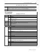

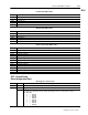
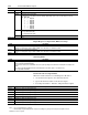
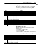
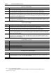
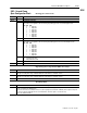
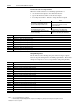
Table Of Contents
- 1771-6.5.88, Plastic Molding Module Reference Manual
- Summary of Changes
- Table of Contents
- Preface
- 1 - Abbreviated Command and Status Blocks
- Chapter Contents
- CLC - Clamp and Eject ERC Values Block
- CPC - Clamp Close Profile Block
- DYC - Dynamic Command Block
- EAC - Ejector Advance Configuration Block
- EPC - Ejector Profile Block
- ERC - Ejector Retract Configuration Block
- FCC - First Clamp Close Configuration Block
- FOC - First Clamp Open Configuration Block
- HDC - Hold Configuration Block
- HPC - Pack/Hold Profile Block
- INC - Injection Configuration Block
- IPC - Injection Profile Block
- JGC - Jog Configuration Block
- LPC - Clamp Low Pressure Close Configuration Block
- MCC - Module Configuration Command Block
- OPC - Clamp Open Profile Block
- OSC - Clamp Open Slow Configuration Block
- PKC - Pack Configuration Block
- PLC - Plastication Configuration Block
- PPC - Plastication Profile Block
- PRC - Pre-decompression Configuration Block
- PSC - Post- decompression Configuration Block
- PTC - Process Trace Configuration Block
- RLC - Inject ERC Values Block
- SCC - Second Clamp Close Configuration Block
- SOC - Second Clamp Open Configuration Block
- TCC - Third Clamp Close Configuration Block
- TOC - Third Clamp Open Configuration Block
- CLS - Clamp and Eject ERC Values Status Block
- CPS - Clamp Close Profiles Status Block
- EPS - Ejector Profile Status Block
- HPS - Pack/Hold Profile Status Block
- IPS - Injection Profile Status Block
- OPS - Clamp Open Profiles Status Block
- PPS - Plastication Profile Status Block
- PTS - Process Trace Status Block
- RLS - Inject ERC Values Status Block
- SYS - System Status Block
- 2 - Command Word/Bit Descriptions
- Alphabetical List of Command Blocks and Block ID Codes
- List of Data Words
- Engineering Units
- Data Blocks Require I/O Configuration
- Data Blocks for System Control
- Data Blocks for Controlling Ram (Screw) Position
- Data Blocks for Controlling Clamp Position
- Data Blocks for Controlling Ejector Position
- Sensors Required
- CLC CLC - Clamp and Eject ERC Values Block
- CPC - Clamp Close Profile Block
- DYC DYC - Dynamic Command Block
- EAC - Ejector Advance Configuration Block
- EPC - Ejector Profile Block
- ERC - Ejector Retract Configuration Block
- FCC - First Clamp Close Configuration Block
- FOC - First Clamp Open Configuration Block
- HDC - Hold Configuration Block
- HPC - Pack/Hold Profile Block
- INC - Injection Configuration Block
- IPC - Injection Profile Block
- JGC - Jog Configuration Block
- LPC - Clamp Low Pressure Close Configuration Block
- MCC - Module Configuration Command Block
- OPC - Clamp Open Profile Block
- OSC - Clamp Open Slow Configuration Block
- PKC - Pack Configuration Block
- PLC Plastication Configuration Command Block (PLC)
- PPC - Plastication Profile Block
- PRC - Pre-decompression Configuration Block
- PSC - Post-decompression Configuration Block
- PTC - Process Trace Configuration Block
- RLC - Inject ERC Values Block
- SCC - Second Clamp Close Configuration Block
- SOC - Second Clamp Open Configuration Block
- TCC - Third Clamp Close Configuration Block
- TOC - Third Clamp Open Configuration Block
- 3 - Word/Bit Descriptions
- List of Status Blocks and Block ID Codes
- List of Data Words
- Data Blocks Require I/O Configuration
- Engineering Units
- Status Block for Reporting System Status
- Status Blocks for Reporting Ram (Screw) Position
- Status Blocks for Reporting Clamp Position
- Status Blocks for Reporting Ejector Position
- CLS - Clamp and Eject ERC Values Status Block
- CPS - Clamp Close Profiles Status Block
- EPS - Ejector Profile Status Block
- HPS - Pack/Hold Profile Status Block
- IPS ú Injection Profile Status Block
- OPS - Clamp Open Profiles Status Block
- PPS - Plastication Profile Status Block
- PTS - Process Trace Status Block
- RLS - Inject ERC Values Status Block
- SYS - System Status Block
- 4 - Programming Error Codes
- 5 - Module Specifications
- 6 - Calibration Instructions
- A - Single transfer for Reporting Ejector Status
- Back cover

2–95Command Word/Bit Descriptions
Publication
1771-6.5.88 – July 1997
PTC
Movement Pressure Alarm Setpoint
Word Description
PSC57 Movement High Pressure Alarm Setpoint [01] The module compares real-time ram (screw) pressure against this entry when ex-
ecuting the Post-decompression Movement. The module sets alarm status bit SYS06-B08 when ram (screw) pressure equals or
exceeds this entry during the Post-decompression Movement. A zero entry inhibits SYS06-B08.
PSC58 - 64 Open
Bit-mapped Control Words
Word Bit Description
PTC01 Block ID = 00011100 (Low Byte). High byte reserved for the module. Do not use.
PTC02 Control bits
B00 0 = Process trace disabled
1 = Process trace enabled
B01 0 = Trigger on time delay
1 = Trigger on position
PTC03 Open
PTC04 Open
PTC05 Trigger delay (in hundredths of seconds) for data collection after injection begins
(when PTC02-B01 = 0)
PTC06 Trigger position (in hundredths of inches or tenths of millimeters) on which to collect data when PTC02-B01 = 1
PTC07 Sample rate at which the module collects trace data in milliseconds (must be an even number between 2 and 230)
PTC08 Trace #1 selection
B01 Injection position
B02 Injection pressure
B03 Injection velocity
The module will return unscaled injection position data if injection velocity is selected. The process trace screen uses
this position information to calculate and display velocity.
B04 Cavity pressure
B05 Screw RPM
B06 Injection flow valve output
B07 Injection pressure valve output
B08 - B15 Reserved Do not use.
PTC09 Trace #2 selection
B01 Injection position
B02 Injection pressure
B03 Injection velocity
The module will return unscaled injection position data if injection velocity is selected. The process trace screen uses
this position information to calculate and display velocity.
B04 Cavity pressure
B05 Screw RPM
B06 Injection flow valve output
B07 Injection pressure valve output
B08 - B15 Reserved Do not use.
PTC – Process Trace
Configuration Block