
User Manual

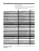
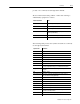
Table Of Contents
- 1771-6.5.88, Plastic Molding Module Reference Manual
- Summary of Changes
- Table of Contents
- Preface
- 1 - Abbreviated Command and Status Blocks
- Chapter Contents
- CLC - Clamp and Eject ERC Values Block
- CPC - Clamp Close Profile Block
- DYC - Dynamic Command Block
- EAC - Ejector Advance Configuration Block
- EPC - Ejector Profile Block
- ERC - Ejector Retract Configuration Block
- FCC - First Clamp Close Configuration Block
- FOC - First Clamp Open Configuration Block
- HDC - Hold Configuration Block
- HPC - Pack/Hold Profile Block
- INC - Injection Configuration Block
- IPC - Injection Profile Block
- JGC - Jog Configuration Block
- LPC - Clamp Low Pressure Close Configuration Block
- MCC - Module Configuration Command Block
- OPC - Clamp Open Profile Block
- OSC - Clamp Open Slow Configuration Block
- PKC - Pack Configuration Block
- PLC - Plastication Configuration Block
- PPC - Plastication Profile Block
- PRC - Pre-decompression Configuration Block
- PSC - Post- decompression Configuration Block
- PTC - Process Trace Configuration Block
- RLC - Inject ERC Values Block
- SCC - Second Clamp Close Configuration Block
- SOC - Second Clamp Open Configuration Block
- TCC - Third Clamp Close Configuration Block
- TOC - Third Clamp Open Configuration Block
- CLS - Clamp and Eject ERC Values Status Block
- CPS - Clamp Close Profiles Status Block
- EPS - Ejector Profile Status Block
- HPS - Pack/Hold Profile Status Block
- IPS - Injection Profile Status Block
- OPS - Clamp Open Profiles Status Block
- PPS - Plastication Profile Status Block
- PTS - Process Trace Status Block
- RLS - Inject ERC Values Status Block
- SYS - System Status Block
- 2 - Command Word/Bit Descriptions
- Alphabetical List of Command Blocks and Block ID Codes
- List of Data Words
- Engineering Units
- Data Blocks Require I/O Configuration
- Data Blocks for System Control
- Data Blocks for Controlling Ram (Screw) Position
- Data Blocks for Controlling Clamp Position
- Data Blocks for Controlling Ejector Position
- Sensors Required
- CLC CLC - Clamp and Eject ERC Values Block
- CPC - Clamp Close Profile Block
- DYC DYC - Dynamic Command Block
- EAC - Ejector Advance Configuration Block
- EPC - Ejector Profile Block
- ERC - Ejector Retract Configuration Block
- FCC - First Clamp Close Configuration Block
- FOC - First Clamp Open Configuration Block
- HDC - Hold Configuration Block
- HPC - Pack/Hold Profile Block
- INC - Injection Configuration Block
- IPC - Injection Profile Block
- JGC - Jog Configuration Block
- LPC - Clamp Low Pressure Close Configuration Block
- MCC - Module Configuration Command Block
- OPC - Clamp Open Profile Block
- OSC - Clamp Open Slow Configuration Block
- PKC - Pack Configuration Block
- PLC Plastication Configuration Command Block (PLC)
- PPC - Plastication Profile Block
- PRC - Pre-decompression Configuration Block
- PSC - Post-decompression Configuration Block
- PTC - Process Trace Configuration Block
- RLC - Inject ERC Values Block
- SCC - Second Clamp Close Configuration Block
- SOC - Second Clamp Open Configuration Block
- TCC - Third Clamp Close Configuration Block
- TOC - Third Clamp Open Configuration Block
- 3 - Word/Bit Descriptions
- List of Status Blocks and Block ID Codes
- List of Data Words
- Data Blocks Require I/O Configuration
- Engineering Units
- Status Block for Reporting System Status
- Status Blocks for Reporting Ram (Screw) Position
- Status Blocks for Reporting Clamp Position
- Status Blocks for Reporting Ejector Position
- CLS - Clamp and Eject ERC Values Status Block
- CPS - Clamp Close Profiles Status Block
- EPS - Ejector Profile Status Block
- HPS - Pack/Hold Profile Status Block
- IPS ú Injection Profile Status Block
- OPS - Clamp Open Profiles Status Block
- PPS - Plastication Profile Status Block
- PTS - Process Trace Status Block
- RLS - Inject ERC Values Status Block
- SYS - System Status Block
- 4 - Programming Error Codes
- 5 - Module Specifications
- 6 - Calibration Instructions
- A - Single transfer for Reporting Ejector Status
- Back cover

PrefaceP–2
Publication
1771-6.5.88 – May 1997
Related Documentation
The following documents contain additional information concerning
Allen-Bradley QDC and PLC products. To obtain a copy, contact
your local Allen-Bradley office or distributor.
For Read This Document
Document
Number
In-depth information on grounding and wiring Allen-Bradley
programmable controllers
Allen-Bradley Programmable Controller Grounding
and Wiring Guidelines
1770-4.1
Selecting your QDC module’s mode of operation and matching it to
your machine’s hydraulics
Plastic Molding Module Application Guide 1771-4.10
Installing and configuring your QDC module to control inject
operations
Plastic Molding Module User Manual 1771-QDC
Inject Mode Operation
1771-6.5.85
Installing and configuring your QDC module to control both inject
and clamp operations
Plastic Molding Module User Manual, 1771-QDC
Inject and Clamp Mode Operation
1771-6.5.86
Installing and configuring your QDC module to control both clamp
and eject operations
Plastic Molding Module User Manual, 1771-QDC
Clamp and Eject Mode Operation
1771-6.5.87
Installing and configuring your QDC module to control inject, clamp,
and eject operations
Plastic Molding Module User Manual, 1771-QDC
Inject, Clamp, and Eject Mode Operation
1771-6.5.93
Selecting instructions and organizing memory when writing ladder
logic to run your machine
1785 PLC-5 Programmable Controller
Instruction Set Reference
1785-6.1
Installing the PLC processor and I/O modules 1785 PLC-5 Programmable Controller Quick Start 1785-10.4
Installing Pro-Set 700 injection molding software Pro-Set 700 Installation Instructions 6500-5.4
Installing your Pro-Set 700 operator interface Pro-Set 700 Operator Interface Installation Manual 6500-6.2.1
Customizing Pro-Set 700 software for your application Pro-Set 700 Software Release 2.1 Reference
Manual
6500-6.4.3
Selecting the Pro-Set 600 software that matches the requirements
of your molding machine
Pro-Set 600 Operator Interface Software for Injection
Molding Designer’s Guide
6500-6.5.11
Transferring your Pro-Set 600 software from a floppy to your hard
drive and adding overlays into your PLC-5 and PanelView
application files
Pro-Set 600 Operator Interface Software for Injection
Molding Software Assembly Manual
6500-6.5.12
Installing Pro-Set 600 overlay(s) into your application files Pro-Set 600 Operator Interface Software for Injection
Molding Software Overlay Installation Manual
6500-6.5.13
Customizing your Pro-Set 600 build for your machine control
requirements.
Pro-Set 600 Operator Interface Software for Injection
Molding Software Customization Manual
6500-6.5.14
Support to customize your software control system. Pro-Set 600 Operator Interface Software for Injection
Molding Software Reference Manual
6500-6.5.15
Setting up your molding machine for use with Pro-Set 700 software Pro-Set 700 Software Release 2.1 User Manual 6500-6.5.18
Using co-injection software Pro-Set 700 Co-injection Software User Manual 6500-6.5.19
Inputting injection molding system setpoints and actuals Pro-Set 700 Systems Jobsetting Guide 6500-6.9.3
Installing modules for co–injection applications Installing Co-injection and Plastic Molding Modules
Quick Start
6500-10.1
A description of important differences between solid-state
programmable controller products and hard-wired
electromechanical devices
Application Considerations for Solid-State Controls SGI-1.1
An article on wire sizes and types for grounding electrical
equipment
National Electrical Code
National Fire
Protection Assoc.
of Boston, MA.
A complete listing of current Allen-Bradley documentation Allen-Bradley Publication Index SD499
A glossary of industrial automation terms and abbreviations Allen-Bradley Industrial Automation Glossary AG-7.1
The following abbreviations, symbols, and terms are specific to this
Abbreviations, Symbols,
and Terms