
User Manual
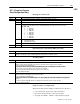
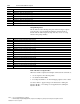
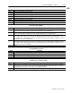
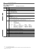
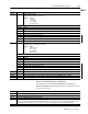
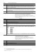
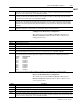
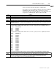
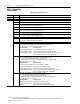
Table Of Contents
- 1771-6.5.88, Plastic Molding Module Reference Manual
- Summary of Changes
- Table of Contents
- Preface
- 1 - Abbreviated Command and Status Blocks
- Chapter Contents
- CLC - Clamp and Eject ERC Values Block
- CPC - Clamp Close Profile Block
- DYC - Dynamic Command Block
- EAC - Ejector Advance Configuration Block
- EPC - Ejector Profile Block
- ERC - Ejector Retract Configuration Block
- FCC - First Clamp Close Configuration Block
- FOC - First Clamp Open Configuration Block
- HDC - Hold Configuration Block
- HPC - Pack/Hold Profile Block
- INC - Injection Configuration Block
- IPC - Injection Profile Block
- JGC - Jog Configuration Block
- LPC - Clamp Low Pressure Close Configuration Block
- MCC - Module Configuration Command Block
- OPC - Clamp Open Profile Block
- OSC - Clamp Open Slow Configuration Block
- PKC - Pack Configuration Block
- PLC - Plastication Configuration Block
- PPC - Plastication Profile Block
- PRC - Pre-decompression Configuration Block
- PSC - Post- decompression Configuration Block
- PTC - Process Trace Configuration Block
- RLC - Inject ERC Values Block
- SCC - Second Clamp Close Configuration Block
- SOC - Second Clamp Open Configuration Block
- TCC - Third Clamp Close Configuration Block
- TOC - Third Clamp Open Configuration Block
- CLS - Clamp and Eject ERC Values Status Block
- CPS - Clamp Close Profiles Status Block
- EPS - Ejector Profile Status Block
- HPS - Pack/Hold Profile Status Block
- IPS - Injection Profile Status Block
- OPS - Clamp Open Profiles Status Block
- PPS - Plastication Profile Status Block
- PTS - Process Trace Status Block
- RLS - Inject ERC Values Status Block
- SYS - System Status Block
- 2 - Command Word/Bit Descriptions
- Alphabetical List of Command Blocks and Block ID Codes
- List of Data Words
- Engineering Units
- Data Blocks Require I/O Configuration
- Data Blocks for System Control
- Data Blocks for Controlling Ram (Screw) Position
- Data Blocks for Controlling Clamp Position
- Data Blocks for Controlling Ejector Position
- Sensors Required
- CLC CLC - Clamp and Eject ERC Values Block
- CPC - Clamp Close Profile Block
- DYC DYC - Dynamic Command Block
- EAC - Ejector Advance Configuration Block
- EPC - Ejector Profile Block
- ERC - Ejector Retract Configuration Block
- FCC - First Clamp Close Configuration Block
- FOC - First Clamp Open Configuration Block
- HDC - Hold Configuration Block
- HPC - Pack/Hold Profile Block
- INC - Injection Configuration Block
- IPC - Injection Profile Block
- JGC - Jog Configuration Block
- LPC - Clamp Low Pressure Close Configuration Block
- MCC - Module Configuration Command Block
- OPC - Clamp Open Profile Block
- OSC - Clamp Open Slow Configuration Block
- PKC - Pack Configuration Block
- PLC Plastication Configuration Command Block (PLC)
- PPC - Plastication Profile Block
- PRC - Pre-decompression Configuration Block
- PSC - Post-decompression Configuration Block
- PTC - Process Trace Configuration Block
- RLC - Inject ERC Values Block
- SCC - Second Clamp Close Configuration Block
- SOC - Second Clamp Open Configuration Block
- TCC - Third Clamp Close Configuration Block
- TOC - Third Clamp Open Configuration Block
- 3 - Word/Bit Descriptions
- List of Status Blocks and Block ID Codes
- List of Data Words
- Data Blocks Require I/O Configuration
- Engineering Units
- Status Block for Reporting System Status
- Status Blocks for Reporting Ram (Screw) Position
- Status Blocks for Reporting Clamp Position
- Status Blocks for Reporting Ejector Position
- CLS - Clamp and Eject ERC Values Status Block
- CPS - Clamp Close Profiles Status Block
- EPS - Ejector Profile Status Block
- HPS - Pack/Hold Profile Status Block
- IPS ú Injection Profile Status Block
- OPS - Clamp Open Profiles Status Block
- PPS - Plastication Profile Status Block
- PTS - Process Trace Status Block
- RLS - Inject ERC Values Status Block
- SYS - System Status Block
- 4 - Programming Error Codes
- 5 - Module Specifications
- 6 - Calibration Instructions
- A - Single transfer for Reporting Ejector Status
- Back cover

2–72 Command Word/Bit Descriptions
Publication
1771-6.5.88 – July 1997
Notes: 1. For [ ] engineering units, see page 3.
2. When using the Inject/Clamp/Eject mode, all pressure readings are system pressure at input 2, except where noted.
Word Description
MCC42 Ejector Position Maximum Software Travel Limit [15] The module continuously compares real-time ejector position against this entry.
The module sets alarm status bitSYS07-B05 and forces all of its outputs to zero when executing an ejector advance profile and ejec-
tor position equals or exceeds this entry. A zero entry inhibits SYS07-B05.
MCC43 Ejector Software Travel Limit Alarm Deadband [17] After sensing an ejector overtravel and latching alarm status bit SYS07-B04 or
SYS07-B05, the module will not unlatch bit until real-time ejector position is inside the overtravel setpoint by an incremental length
equal to this entry. This incremental position will be added to MCC41 in order to determine the ejector position required to unlatch
SYS07-B04. This incremental position will be subtracted from MCC42 in order to determine the ejector position required to unlatch
SYS07-B05.
MCC44 Ejector Position Transducer Digital Filter [23] A non-zero entry forces the module to filter the input before using the result for all
ejector position calculations. Use this parameter to soften the input signal from a linear potentiometer.
Ejector Pressure Transducer Configuration
The module accesses data in MCC45-MCC50 if bit patterns in
MCC02 and MCC03 indicate that the module is connected to an
ejector pressure sensor.
Word Description
MCC45 Minimum Ejector Pressure [03]
MCC46 Maximum Ejector Pressure [03]
MCC47 Analog Signal at Minimum Ejector Pressure [24]
MCC48 Analog Signal at Maximum Ejector Pressure [24]
MCC49 High Ejector Pressure Alarm Setpoint [03] The module continuously compares real-time ejector pressure against this entry. The
module sets alarm status bit SYS05-B02 when ejector pressure equals or exceeds this entry. A zero entry inhibits SYS05-B02.
MCC50 Ejector Pressure Alarm Time Delay [23] Total time the module must monitor a continuous ejector pressure in excess of the non-zero
entry in all ejector pressure alarm setpoints before setting the associated alarm status bit. Setpoint/bit pairs affected are:
Setpoint Alarm Status Bit
MCC49 SYS05-B02
JGC08 SYS05-B11
EAC57 SYS06-B13
Use a non-zero entry in this word to filter out ejector pressure spikes of short enough duration to avoid nuisance alarms.
Screw RPM Transducer Configuration
The module accesses data in MCC51 - 56 if bit patterns in MCC02 and
MCC03 indicate that the module is connected to a screw RPM sensor.
Word Description
MCC51 Minimum Screw RPM [25]
MCC52 Maximum Screw RPM [25]
MCC53 Analog Signal at Minimum Screw RPM [24]
MCC54 Analog Signal at Maximum Screw RPM [24]
MCC55 High Screw RPM Alarm Setpoint [25] The module continuously compares real-time screw RPM against this entry. The module sets
alarm status bit SYS05-B03 when screw RPM equals or exceeds this entry. A zero entry inhibits SYS05-B03.
MCC56 High Screw RPM Alarm Time Delay [23] Total time the module must monitor a continuous screw RPM in excess of the non-zero
entry in all screw RPM alarm setpoints before setting the associated alarm status bit. Setpoint/bitpairs affected are:
Setpoint Alarm Status Bit
MCC55 SYS05-B03
JGC05 SYS05-B08
Use a non-zero entry in this word to filter out screw RPM spikes of short enough duration to avoid nuisance alarms.