
User Manual
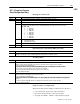
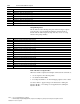
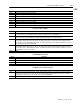
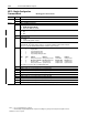
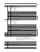
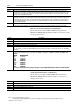
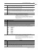
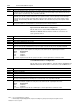
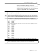
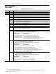
Table Of Contents
- 1771-6.5.88, Plastic Molding Module Reference Manual
- Summary of Changes
- Table of Contents
- Preface
- 1 - Abbreviated Command and Status Blocks
- Chapter Contents
- CLC - Clamp and Eject ERC Values Block
- CPC - Clamp Close Profile Block
- DYC - Dynamic Command Block
- EAC - Ejector Advance Configuration Block
- EPC - Ejector Profile Block
- ERC - Ejector Retract Configuration Block
- FCC - First Clamp Close Configuration Block
- FOC - First Clamp Open Configuration Block
- HDC - Hold Configuration Block
- HPC - Pack/Hold Profile Block
- INC - Injection Configuration Block
- IPC - Injection Profile Block
- JGC - Jog Configuration Block
- LPC - Clamp Low Pressure Close Configuration Block
- MCC - Module Configuration Command Block
- OPC - Clamp Open Profile Block
- OSC - Clamp Open Slow Configuration Block
- PKC - Pack Configuration Block
- PLC - Plastication Configuration Block
- PPC - Plastication Profile Block
- PRC - Pre-decompression Configuration Block
- PSC - Post- decompression Configuration Block
- PTC - Process Trace Configuration Block
- RLC - Inject ERC Values Block
- SCC - Second Clamp Close Configuration Block
- SOC - Second Clamp Open Configuration Block
- TCC - Third Clamp Close Configuration Block
- TOC - Third Clamp Open Configuration Block
- CLS - Clamp and Eject ERC Values Status Block
- CPS - Clamp Close Profiles Status Block
- EPS - Ejector Profile Status Block
- HPS - Pack/Hold Profile Status Block
- IPS - Injection Profile Status Block
- OPS - Clamp Open Profiles Status Block
- PPS - Plastication Profile Status Block
- PTS - Process Trace Status Block
- RLS - Inject ERC Values Status Block
- SYS - System Status Block
- 2 - Command Word/Bit Descriptions
- Alphabetical List of Command Blocks and Block ID Codes
- List of Data Words
- Engineering Units
- Data Blocks Require I/O Configuration
- Data Blocks for System Control
- Data Blocks for Controlling Ram (Screw) Position
- Data Blocks for Controlling Clamp Position
- Data Blocks for Controlling Ejector Position
- Sensors Required
- CLC CLC - Clamp and Eject ERC Values Block
- CPC - Clamp Close Profile Block
- DYC DYC - Dynamic Command Block
- EAC - Ejector Advance Configuration Block
- EPC - Ejector Profile Block
- ERC - Ejector Retract Configuration Block
- FCC - First Clamp Close Configuration Block
- FOC - First Clamp Open Configuration Block
- HDC - Hold Configuration Block
- HPC - Pack/Hold Profile Block
- INC - Injection Configuration Block
- IPC - Injection Profile Block
- JGC - Jog Configuration Block
- LPC - Clamp Low Pressure Close Configuration Block
- MCC - Module Configuration Command Block
- OPC - Clamp Open Profile Block
- OSC - Clamp Open Slow Configuration Block
- PKC - Pack Configuration Block
- PLC Plastication Configuration Command Block (PLC)
- PPC - Plastication Profile Block
- PRC - Pre-decompression Configuration Block
- PSC - Post-decompression Configuration Block
- PTC - Process Trace Configuration Block
- RLC - Inject ERC Values Block
- SCC - Second Clamp Close Configuration Block
- SOC - Second Clamp Open Configuration Block
- TCC - Third Clamp Close Configuration Block
- TOC - Third Clamp Open Configuration Block
- 3 - Word/Bit Descriptions
- List of Status Blocks and Block ID Codes
- List of Data Words
- Data Blocks Require I/O Configuration
- Engineering Units
- Status Block for Reporting System Status
- Status Blocks for Reporting Ram (Screw) Position
- Status Blocks for Reporting Clamp Position
- Status Blocks for Reporting Ejector Position
- CLS - Clamp and Eject ERC Values Status Block
- CPS - Clamp Close Profiles Status Block
- EPS - Ejector Profile Status Block
- HPS - Pack/Hold Profile Status Block
- IPS ú Injection Profile Status Block
- OPS - Clamp Open Profiles Status Block
- PPS - Plastication Profile Status Block
- PTS - Process Trace Status Block
- RLS - Inject ERC Values Status Block
- SYS - System Status Block
- 4 - Programming Error Codes
- 5 - Module Specifications
- 6 - Calibration Instructions
- A - Single transfer for Reporting Ejector Status
- Back cover

2–69Command Word/Bit Descriptions
Publication
1771-6.5.88 – July 1997
MCC
Word Bit Description
MCC03 MCC Input Range Selection
All inputs have the following range selections:
Byy Bxx Range
0 0 0 to 10 V dc
0 1 1 to 5 V dc
1 0 4 to 20 mA dc
1 1 Not Connected
Use these bit pairs to select the input range:
B01 B00 Input #1
B03 B02 Input #2
B05 B04 Input #3
B07 B06 Input #4
B09 B08 Input #5 Both of these bits must be SET.
B11 B10 Input #6 Both of these bits must be SET.
B13 B12 Input #7 Both of these bits must be SET.
B15 B14 Input #8 Both of these bits must be SET.
MCC04 MCC Output Range Selection
All outputs have the following range selections:
Byy Bxx Range
0 0 –10 to +10 V dc
0 1 0 to +10 V dc
1 0 4 to 20 mA dc
1 1 Not Connected
Use these bit pairs to select the output range:
B01 B00 Output #1
B03 B02 Output #2
B05 B04 Output #3
B07 B06 Output #4
B09 B08 Output #5 Both of these bits must be SET.
B11 B10 Output #6 Both of these bits must be SET.
B13 B12 Output #7 Both of these bits must be SET.
B15 B14 Output #8 Both of these bits must be SET.
MCC05 Adds percentage offset up to
"
10% (–1000 to +1000) to Stop Position of Output #1 (0 V dc or 4 mA).
MCC06 Adds percentage offset up to
"
10% (–1000 to +1000) to Stop Position of Output #2 (0 V dc or 4 mA).
MCC07 Adds percentage offset up to
"
10% (–1000 to +1000) to Stop Position of Output #3 (0 V dc or 4 mA).
MCC08 Adds percentage offset up to
"
10% (–1000 to +1000) to Stop Position of Output #4 (0 V dc or 4 mA).
Ram (Screw) Position Transducer Configuration
The module accesses data in MCC09-MCC16 if bit patterns in
MCC02 and MCC03 indicate that the module is connected to a ram
(screw) position sensor.
Word Description
MCC09 Minimum Ram (Screw) Position [11]
MCC10 Maximum Ram (Screw) Position [11]
MCC11 Analog Signal at Minimum Ram (Screw) Position [24]
MCC12 Analog Signal at Maximum Ram (Screw) Position [24] The module continuously compares real-time ram (screw) position against
this entry. The module sets alarm status bit SYS07-B00 and forces all of its outputs to zero when executing a ram (screw) forward
profile (Injection, Pack, Hold) and ram (screw) position is less than or equals this entry. A zero entry inhibits SYS07-B00.
MCC13 Ram (Screw) Position Minimum Software Travel Limit [11]