
User Manual
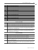
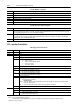
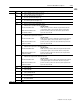
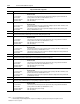
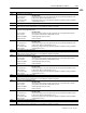
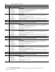
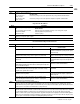
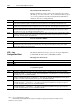
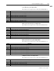
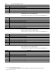
Table Of Contents
- 1771-6.5.88, Plastic Molding Module Reference Manual
- Summary of Changes
- Table of Contents
- Preface
- 1 - Abbreviated Command and Status Blocks
- Chapter Contents
- CLC - Clamp and Eject ERC Values Block
- CPC - Clamp Close Profile Block
- DYC - Dynamic Command Block
- EAC - Ejector Advance Configuration Block
- EPC - Ejector Profile Block
- ERC - Ejector Retract Configuration Block
- FCC - First Clamp Close Configuration Block
- FOC - First Clamp Open Configuration Block
- HDC - Hold Configuration Block
- HPC - Pack/Hold Profile Block
- INC - Injection Configuration Block
- IPC - Injection Profile Block
- JGC - Jog Configuration Block
- LPC - Clamp Low Pressure Close Configuration Block
- MCC - Module Configuration Command Block
- OPC - Clamp Open Profile Block
- OSC - Clamp Open Slow Configuration Block
- PKC - Pack Configuration Block
- PLC - Plastication Configuration Block
- PPC - Plastication Profile Block
- PRC - Pre-decompression Configuration Block
- PSC - Post- decompression Configuration Block
- PTC - Process Trace Configuration Block
- RLC - Inject ERC Values Block
- SCC - Second Clamp Close Configuration Block
- SOC - Second Clamp Open Configuration Block
- TCC - Third Clamp Close Configuration Block
- TOC - Third Clamp Open Configuration Block
- CLS - Clamp and Eject ERC Values Status Block
- CPS - Clamp Close Profiles Status Block
- EPS - Ejector Profile Status Block
- HPS - Pack/Hold Profile Status Block
- IPS - Injection Profile Status Block
- OPS - Clamp Open Profiles Status Block
- PPS - Plastication Profile Status Block
- PTS - Process Trace Status Block
- RLS - Inject ERC Values Status Block
- SYS - System Status Block
- 2 - Command Word/Bit Descriptions
- Alphabetical List of Command Blocks and Block ID Codes
- List of Data Words
- Engineering Units
- Data Blocks Require I/O Configuration
- Data Blocks for System Control
- Data Blocks for Controlling Ram (Screw) Position
- Data Blocks for Controlling Clamp Position
- Data Blocks for Controlling Ejector Position
- Sensors Required
- CLC CLC - Clamp and Eject ERC Values Block
- CPC - Clamp Close Profile Block
- DYC DYC - Dynamic Command Block
- EAC - Ejector Advance Configuration Block
- EPC - Ejector Profile Block
- ERC - Ejector Retract Configuration Block
- FCC - First Clamp Close Configuration Block
- FOC - First Clamp Open Configuration Block
- HDC - Hold Configuration Block
- HPC - Pack/Hold Profile Block
- INC - Injection Configuration Block
- IPC - Injection Profile Block
- JGC - Jog Configuration Block
- LPC - Clamp Low Pressure Close Configuration Block
- MCC - Module Configuration Command Block
- OPC - Clamp Open Profile Block
- OSC - Clamp Open Slow Configuration Block
- PKC - Pack Configuration Block
- PLC Plastication Configuration Command Block (PLC)
- PPC - Plastication Profile Block
- PRC - Pre-decompression Configuration Block
- PSC - Post-decompression Configuration Block
- PTC - Process Trace Configuration Block
- RLC - Inject ERC Values Block
- SCC - Second Clamp Close Configuration Block
- SOC - Second Clamp Open Configuration Block
- TCC - Third Clamp Close Configuration Block
- TOC - Third Clamp Open Configuration Block
- 3 - Word/Bit Descriptions
- List of Status Blocks and Block ID Codes
- List of Data Words
- Data Blocks Require I/O Configuration
- Engineering Units
- Status Block for Reporting System Status
- Status Blocks for Reporting Ram (Screw) Position
- Status Blocks for Reporting Clamp Position
- Status Blocks for Reporting Ejector Position
- CLS - Clamp and Eject ERC Values Status Block
- CPS - Clamp Close Profiles Status Block
- EPS - Ejector Profile Status Block
- HPS - Pack/Hold Profile Status Block
- IPS ú Injection Profile Status Block
- OPS - Clamp Open Profiles Status Block
- PPS - Plastication Profile Status Block
- PTS - Process Trace Status Block
- RLS - Inject ERC Values Status Block
- SYS - System Status Block
- 4 - Programming Error Codes
- 5 - Module Specifications
- 6 - Calibration Instructions
- A - Single transfer for Reporting Ejector Status
- Back cover

2–62 Command Word/Bit Descriptions
Publication
1771-6.5.88 – July 1997
Notes: 1. For [ ] engineering units, see page 3.
2. When using the Inject/Clamp/Eject mode, all pressure readings are system pressure at input 2, except where noted.
Injection Transition Parameters
Injection transition-to-pack or hold occurs when the four words in
this table go to a state of non-zero. If you want the module to ignore
one or more parameters when monitoring the Injection Profile for
transition, enter zero for that parameter.
Word Description
IPC60 Time Limit for Transition [21] The module immediately terminates the Injection Profile and begins the Pack(Hold) Profile if the total
Injection Profile execution time equals or exceeds the non-zero entry in this word. The module ignores this parameter if zero.
IPC61 Ram (Screw) Position for Transition [12] The module immediately terminates the Injection Profile and begins the Pack(Hold) Profile
if real-time ram (screw) position is less than or equal to the non-zero entry in this word. The module ignores this parameter if zero.
IPC62 Ram (Screw) Pressure for Transition [01] If real-time ram (screw) position is less than or equal to any non-zero entry in IPC64, the
module immediately terminates the Injection Profile and begins the Pack(Hold) Profile if real-time ram (screw) pressure equals or
exceeds this non-zero entry. The module ignores this parameter if zero.
IPC63 Cavity Pressure for Transition [04] If real-time ram (screw) position is less than or equal to any non-zero entry in IPC64, the module
immediately terminates the Injection Profile and begins the Pack(Hold) Profile if real-time cavity pressure equals or exceeds this
non-zero entry. The module ignores this setpoint if zero.
Pressure Transition Inhibit
Word Description
IPC64 Ram (Screw) Position for Pressure Transition Inhibit [12] A non-zero entry forces the module to ignore any non-zero IPC62 and
IPC63 until ram (screw) position is equal to or less than this entry. A zero entry forces the module to use any non-zero entry in
IPC62 and IPC63 during the entire Injection Profile.
The The module will not accept or process the Jog Configuration
Command Block unless it has a valid MCC installed.
Bit-mapped Control Words
Word Description
JGC01 Block ID = 00000010 (Low byte). High byte reserved for the module. Do not use
JGC02 - 04 Open
Jog Alarm Setpoints
Word Description
JGC05 Screw Rotate Jog RPM Alarm Setpoint [25] The module compares real-time screw RPM against this entry when responding to
command bit DYC01-B09 = 1. The module sets alarm status bit SYS05-B08 when screw RPM equals or exceeds this entry during a
Screw Rotate Jog. A zero entry inhibits SYS05-B08.
JGC06 Ram (Screw) Jog Pressure Alarm Setpoint [01] The module compares real-time ram (screw) pressure against this entry when re-
sponding to command bit DYC01-B10 = 1 or DYC01-B11 = 1. The module sets alarm status bit SYS05-B09 when ram (screw) pres-
sure equals or exceeds this entry during a Ram (Screw) Jog. A zero entry inhibits SYS05-B09.
JGC07 Clamp Jog Pressure Alarm Setpoint [02] The module compares real-time clamp pressure against this entry when responding to
command bit DYC01-B12 = 1 or DYC01-B13 = 1. The module sets alarm status bit SYS05-B10 when clamp pressure equals or
exceeds this entry during a Clamp Jog. A zero entry inhibits SYS05-B10.
JGC08 Ejector Jog Pressure Alarm Setpoint [03] the module compares real-time ejector pressure against this entry when responding to
command bit DYC01-B14 = 1 or DYC01-B15 = 1. The module sets alarm status bit SYS05-B11 when ejector pressure equals or
exceeds this entry during an Ejector Jog. A zero entry inhibits SYS05-B11.
JGC – Jog
Configuration Block