
User Manual
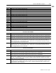
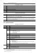
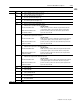
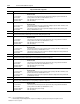
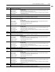
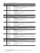
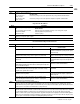
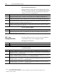
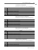
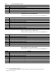
Table Of Contents
- 1771-6.5.88, Plastic Molding Module Reference Manual
- Summary of Changes
- Table of Contents
- Preface
- 1 - Abbreviated Command and Status Blocks
- Chapter Contents
- CLC - Clamp and Eject ERC Values Block
- CPC - Clamp Close Profile Block
- DYC - Dynamic Command Block
- EAC - Ejector Advance Configuration Block
- EPC - Ejector Profile Block
- ERC - Ejector Retract Configuration Block
- FCC - First Clamp Close Configuration Block
- FOC - First Clamp Open Configuration Block
- HDC - Hold Configuration Block
- HPC - Pack/Hold Profile Block
- INC - Injection Configuration Block
- IPC - Injection Profile Block
- JGC - Jog Configuration Block
- LPC - Clamp Low Pressure Close Configuration Block
- MCC - Module Configuration Command Block
- OPC - Clamp Open Profile Block
- OSC - Clamp Open Slow Configuration Block
- PKC - Pack Configuration Block
- PLC - Plastication Configuration Block
- PPC - Plastication Profile Block
- PRC - Pre-decompression Configuration Block
- PSC - Post- decompression Configuration Block
- PTC - Process Trace Configuration Block
- RLC - Inject ERC Values Block
- SCC - Second Clamp Close Configuration Block
- SOC - Second Clamp Open Configuration Block
- TCC - Third Clamp Close Configuration Block
- TOC - Third Clamp Open Configuration Block
- CLS - Clamp and Eject ERC Values Status Block
- CPS - Clamp Close Profiles Status Block
- EPS - Ejector Profile Status Block
- HPS - Pack/Hold Profile Status Block
- IPS - Injection Profile Status Block
- OPS - Clamp Open Profiles Status Block
- PPS - Plastication Profile Status Block
- PTS - Process Trace Status Block
- RLS - Inject ERC Values Status Block
- SYS - System Status Block
- 2 - Command Word/Bit Descriptions
- Alphabetical List of Command Blocks and Block ID Codes
- List of Data Words
- Engineering Units
- Data Blocks Require I/O Configuration
- Data Blocks for System Control
- Data Blocks for Controlling Ram (Screw) Position
- Data Blocks for Controlling Clamp Position
- Data Blocks for Controlling Ejector Position
- Sensors Required
- CLC CLC - Clamp and Eject ERC Values Block
- CPC - Clamp Close Profile Block
- DYC DYC - Dynamic Command Block
- EAC - Ejector Advance Configuration Block
- EPC - Ejector Profile Block
- ERC - Ejector Retract Configuration Block
- FCC - First Clamp Close Configuration Block
- FOC - First Clamp Open Configuration Block
- HDC - Hold Configuration Block
- HPC - Pack/Hold Profile Block
- INC - Injection Configuration Block
- IPC - Injection Profile Block
- JGC - Jog Configuration Block
- LPC - Clamp Low Pressure Close Configuration Block
- MCC - Module Configuration Command Block
- OPC - Clamp Open Profile Block
- OSC - Clamp Open Slow Configuration Block
- PKC - Pack Configuration Block
- PLC Plastication Configuration Command Block (PLC)
- PPC - Plastication Profile Block
- PRC - Pre-decompression Configuration Block
- PSC - Post-decompression Configuration Block
- PTC - Process Trace Configuration Block
- RLC - Inject ERC Values Block
- SCC - Second Clamp Close Configuration Block
- SOC - Second Clamp Open Configuration Block
- TCC - Third Clamp Close Configuration Block
- TOC - Third Clamp Open Configuration Block
- 3 - Word/Bit Descriptions
- List of Status Blocks and Block ID Codes
- List of Data Words
- Data Blocks Require I/O Configuration
- Engineering Units
- Status Block for Reporting System Status
- Status Blocks for Reporting Ram (Screw) Position
- Status Blocks for Reporting Clamp Position
- Status Blocks for Reporting Ejector Position
- CLS - Clamp and Eject ERC Values Status Block
- CPS - Clamp Close Profiles Status Block
- EPS - Ejector Profile Status Block
- HPS - Pack/Hold Profile Status Block
- IPS ú Injection Profile Status Block
- OPS - Clamp Open Profiles Status Block
- PPS - Plastication Profile Status Block
- PTS - Process Trace Status Block
- RLS - Inject ERC Values Status Block
- SYS - System Status Block
- 4 - Programming Error Codes
- 5 - Module Specifications
- 6 - Calibration Instructions
- A - Single transfer for Reporting Ejector Status
- Back cover
2–61Command Word/Bit Descriptions
Publication
1771-6.5.88 – July 1997
IPC
Word Description
IPC50 Segment 11 Pressure Setpoint [01]
if: then the module:
you select Press/Pos controls ram (screw) pressure to this setpoint from ram (screw) position IPC47 until transition
profile execution
you select Press/Time controls ram (screw) pressure to this setpoint at completion of Segment 10 until transition
profile execution
Injection Profile Offsets
Word Description
IPC51 Profile Velocity Offset [05] or [06]
if: then the module:
you select Vel/Pos profile execution applies this entry (after reading the sign bit) to each velocity profile setpoint
IPC03-B14 is RESET reads this parameter in percent velocity
IPC03-B14 is SET reads it in in.(mm)/s
IPC52 Profile Pressure Offset [01] If you select Press/Pos or Press/Time profile execution, the module applies this entry (after reading the
sign bit) to each pressure profile setpoint.
IPC53 - 56 Open
Pressure Limited Injection Parameters
Word Description
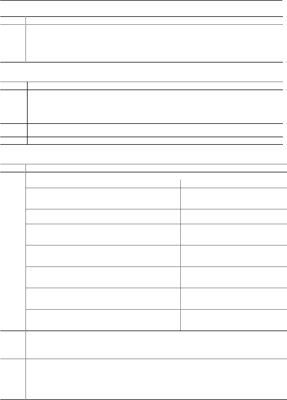
IPC57 Ram (Screw) Pressure Limit for Vel/Pos Injection Profile [01], Profile Velocity Offset [05] or [06]
if: then the module:
you select Pressure Limited Vel/Pos profile execution limits action of the selected valve(s) during the Injec-
tion Profile to maintain ram (screw) pressure equal to
or below this entry
ram (screw) pressure equals or exceeds this entry during a Pressure Limited
Injection Profile and ram (screw) position is equal to or less than IPC58
sets the applicable status bit in IPS05 and freezes
output to selected
velocity
valve for time period IPC59
ram (screw) pressure equals or exceeds this entry after expiration of time
delay IPC59
continues Injection Profile execution using its internal
PID algorithm with this entry used as the algorithm
setpoint
the module switches to PID control during a Pressure Limited Injection Profile,
and bit pattern in INC02 requires the module to control injection velocity and
pressure with different outputs
returns the selected velocity valve to its profile Set-
output value as defined in INC09-INC16
the module switches to the PID algorithm during a Pressure Limited Injection
Profile, and the actual ram (screw) velocity equals or exceeds the velocity
setpoint for the segment under execution
freezes output to selected
pressure
valve for time
period IPC59
the actual ram (screw) velocity equals or exceeds the velocity setpoint after
expiration of time delay IPC59
returns to the VelFF mode of profile execution to drive
the selected
velocity
valve using the segment’s pro-
grammed setpoint
the module returns to VelFF control during a Pressure Limited Injection
Profile, and bit pattern in INC02 requires the module to control injection
velocity and pressure with different outputs
returns the selected
pressure
valve to its profile Set-
output value as defined in INC09-INC16
IPC58 Ram (Screw) Position for Pressure Limiting Inhibit [12]
A non-zero entry forces the module to ignore the magnitude of ram (screw) pressure during a Pressure Limited Vel/Pos Injection
Profile until ram (screw) position is equal to or less than this entry. A zero entry forces the module to pressure limit the entire Injection
Profile if you have selected Pressure Limited Vel/Pos as the profile mode.
IPC59 Algorithm Change Time Delay During Pressure Limit [23]
Total time that the module must monitor a continuous ram (screw) pressure in excess of the non-zero entry in IPC57 before changing
to its internal PID algorithm for continuing a Pressure Limited Vel/Pos Injection Profile. Also the total time that the module must
monitor a continuous ram (screw) velocity greater than the programmed setpoint before changing back to its internal VelFF algorithm
during a Pressure Limited Vel/Pos Injection Profile that has entered pressure limit. Use a non-zero entry to filter out early ram (screw)
pressure spikes of short duration to avoid pressure limiting during the Injection Profile.