
User Manual
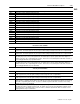
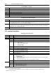
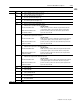
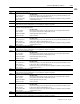
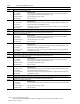
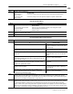
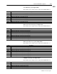
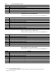
Table Of Contents
- 1771-6.5.88, Plastic Molding Module Reference Manual
- Summary of Changes
- Table of Contents
- Preface
- 1 - Abbreviated Command and Status Blocks
- Chapter Contents
- CLC - Clamp and Eject ERC Values Block
- CPC - Clamp Close Profile Block
- DYC - Dynamic Command Block
- EAC - Ejector Advance Configuration Block
- EPC - Ejector Profile Block
- ERC - Ejector Retract Configuration Block
- FCC - First Clamp Close Configuration Block
- FOC - First Clamp Open Configuration Block
- HDC - Hold Configuration Block
- HPC - Pack/Hold Profile Block
- INC - Injection Configuration Block
- IPC - Injection Profile Block
- JGC - Jog Configuration Block
- LPC - Clamp Low Pressure Close Configuration Block
- MCC - Module Configuration Command Block
- OPC - Clamp Open Profile Block
- OSC - Clamp Open Slow Configuration Block
- PKC - Pack Configuration Block
- PLC - Plastication Configuration Block
- PPC - Plastication Profile Block
- PRC - Pre-decompression Configuration Block
- PSC - Post- decompression Configuration Block
- PTC - Process Trace Configuration Block
- RLC - Inject ERC Values Block
- SCC - Second Clamp Close Configuration Block
- SOC - Second Clamp Open Configuration Block
- TCC - Third Clamp Close Configuration Block
- TOC - Third Clamp Open Configuration Block
- CLS - Clamp and Eject ERC Values Status Block
- CPS - Clamp Close Profiles Status Block
- EPS - Ejector Profile Status Block
- HPS - Pack/Hold Profile Status Block
- IPS - Injection Profile Status Block
- OPS - Clamp Open Profiles Status Block
- PPS - Plastication Profile Status Block
- PTS - Process Trace Status Block
- RLS - Inject ERC Values Status Block
- SYS - System Status Block
- 2 - Command Word/Bit Descriptions
- Alphabetical List of Command Blocks and Block ID Codes
- List of Data Words
- Engineering Units
- Data Blocks Require I/O Configuration
- Data Blocks for System Control
- Data Blocks for Controlling Ram (Screw) Position
- Data Blocks for Controlling Clamp Position
- Data Blocks for Controlling Ejector Position
- Sensors Required
- CLC CLC - Clamp and Eject ERC Values Block
- CPC - Clamp Close Profile Block
- DYC DYC - Dynamic Command Block
- EAC - Ejector Advance Configuration Block
- EPC - Ejector Profile Block
- ERC - Ejector Retract Configuration Block
- FCC - First Clamp Close Configuration Block
- FOC - First Clamp Open Configuration Block
- HDC - Hold Configuration Block
- HPC - Pack/Hold Profile Block
- INC - Injection Configuration Block
- IPC - Injection Profile Block
- JGC - Jog Configuration Block
- LPC - Clamp Low Pressure Close Configuration Block
- MCC - Module Configuration Command Block
- OPC - Clamp Open Profile Block
- OSC - Clamp Open Slow Configuration Block
- PKC - Pack Configuration Block
- PLC Plastication Configuration Command Block (PLC)
- PPC - Plastication Profile Block
- PRC - Pre-decompression Configuration Block
- PSC - Post-decompression Configuration Block
- PTC - Process Trace Configuration Block
- RLC - Inject ERC Values Block
- SCC - Second Clamp Close Configuration Block
- SOC - Second Clamp Open Configuration Block
- TCC - Third Clamp Close Configuration Block
- TOC - Third Clamp Open Configuration Block
- 3 - Word/Bit Descriptions
- List of Status Blocks and Block ID Codes
- List of Data Words
- Data Blocks Require I/O Configuration
- Engineering Units
- Status Block for Reporting System Status
- Status Blocks for Reporting Ram (Screw) Position
- Status Blocks for Reporting Clamp Position
- Status Blocks for Reporting Ejector Position
- CLS - Clamp and Eject ERC Values Status Block
- CPS - Clamp Close Profiles Status Block
- EPS - Ejector Profile Status Block
- HPS - Pack/Hold Profile Status Block
- IPS ú Injection Profile Status Block
- OPS - Clamp Open Profiles Status Block
- PPS - Plastication Profile Status Block
- PTS - Process Trace Status Block
- RLS - Inject ERC Values Status Block
- SYS - System Status Block
- 4 - Programming Error Codes
- 5 - Module Specifications
- 6 - Calibration Instructions
- A - Single transfer for Reporting Ejector Status
- Back cover
2–55Command Word/Bit Descriptions
Publication
1771-6.5.88 – July 1997
INC
Word Description
INC17 Output #1 Acceleration Ramp Rate during Profile [20]
INC18 Output #2 Acceleration Ramp Rate during Profile [20]
INC19 Output #3 Acceleration Ramp Rate during Profile [20]
INC20 Output #4 Acceleration Ramp Rate during Profile [20]
INC21 Output #5 Acceleration Ramp Rate during Profile [20]
INC22 Output #6 Acceleration Ramp Rate during Profile [20]
INC23 Output #7 Acceleration Ramp Rate during Profile [20]
INC24 Output #8 Acceleration Ramp Rate during Profile [20]
INC25 Output #1 Deceleration Ramp Rate during Profile [20]
INC26 Output #2 Deceleration Ramp Rate during Profile [20]
INC27 Output #3 Deceleration Ramp Rate during Profile [20]
INC28 Output #4 Deceleration Ramp Rate during Profile [20]
INC29 Output #5 Deceleration Ramp Rate during Profile [20]
INC30 Output #6 Deceleration Ramp Rate during Profile [20]
INC31 Output #7 Deceleration Ramp Rate during Profile [20]
INC32 Output #8 Deceleration Ramp Rate during Profile [20]
INC33 - 40 Open
Pressure Control Limits
Word Description
INC41 Pressure Minimum Control Limit [01] Minimum controllable ram (screw) pressure attainable during any Press/Pos or Press/Time
Injection Profile. The module expects this ram (screw) pressure when setting its selected pressure valve to the %-output in INC43.
INC42 Pressure Maximum Control Limit [01] Maximum controllable ram (screw) pressure attainable during any Press/Pos or Press/Time
Injection Profile. The module expects this ram (screw) pressure when setting its selected pressure valve to the %-output in INC44.
INC43 Selected Pressure Valve Output for Minimum [19] 0% CV output percentage that the module uses to drive the selected pressure
valve during any Press/Pos or Press/Time Injection Profile. The module expects a pressure equal to INC41 when setting the se-
lected pressure valve to this %-output during profile execution. The Press/Pos or Press/Time Injection Profile will be executed as a
reverse-acting algorithm if this entry is greater than INC44.
INC44 Selected Pressure Valve Output for Maximum [19] 100% CV output percentage that the module uses to drive the selected pressure
valve during any Press/Pos or Press/Time Injection Profile. The module expects a pressure equal to INC42 when setting the se-
lected pressure valve to this %-output during profile execution. The Press/Pos or Press/Time Injection Profile will be executed as a
reverse-acting algorithm if this entry is less than INC43.
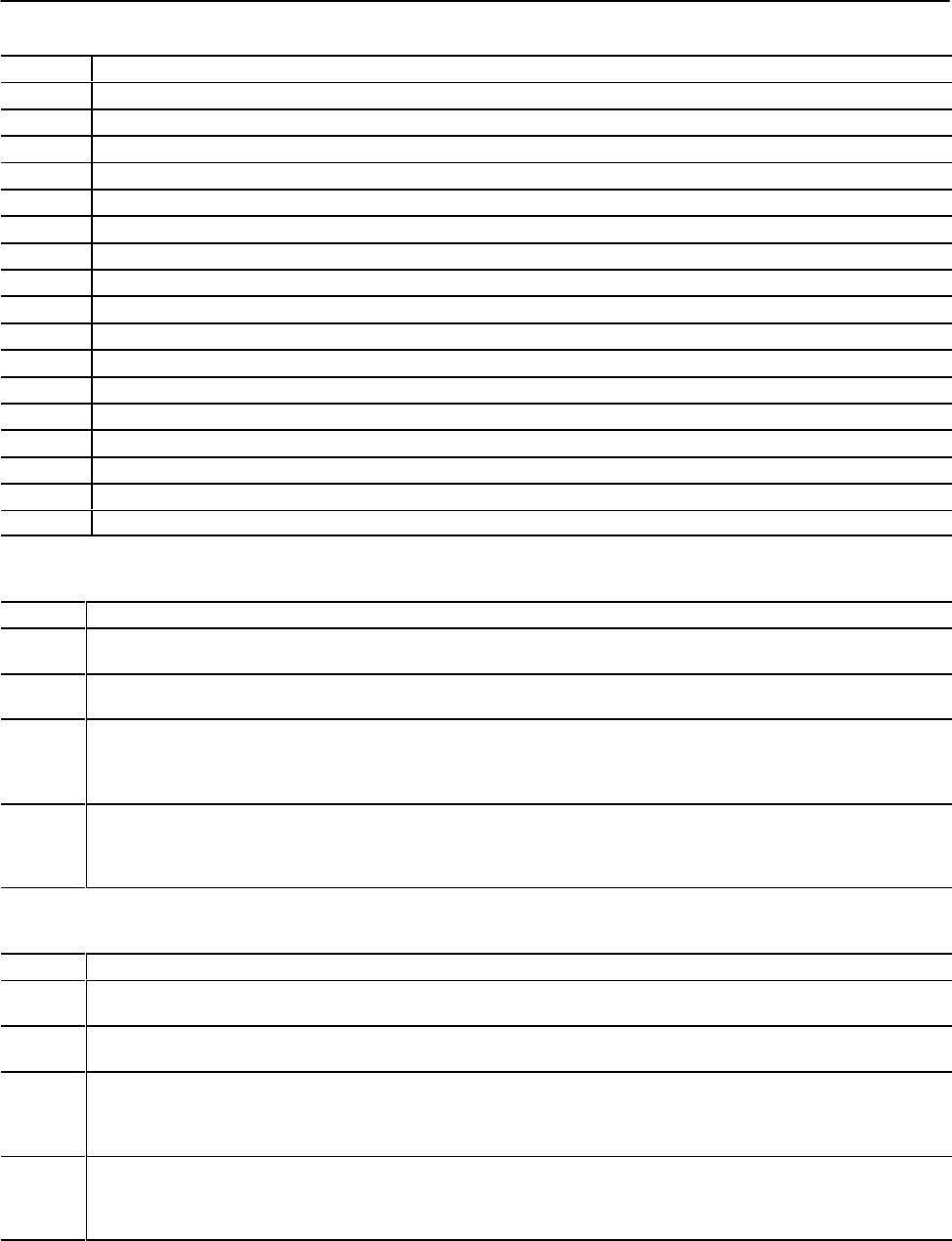
Velocity Control Limits
Word Description
INC45 Velocity Minimum Control Limit [06] Minimum controllable ram (screw) velocity attainable during any Vel/Pos Injection Profile. The
module expects this ram (screw) velocity when setting its selected velocity valve to the %-output in INC47.
INC46 Velocity Maximum Control Limit [06] Maximum controllable ram (screw) velocity attainable during any Vel/Pos Injection Profile. The
module expects this ram (screw) velocity when setting its selected velocity valve to the %-output in INC48.
INC47 Selected Velocity Valve Output for Minimum [19] 0% CV output percentage that the module uses to drive the selected velocity valve
during any Vel/Pos or LimVel/Pos Injection Profile. The module expects a velocity equal to INC45 when setting the selected velocity
valve to this %-output during profile execution. The Vel/Pos or LimVel/Pos Injection Profile will be executed as a reverse-acting
algorithm if this entry is greater than INC48.
INC48 Selected Velocity Valve Output for Maximum [19] 100% CV output percentage that the module uses to drive the selected velocity
valve during any Vel/Pos or LimVel/Pos Injection Profile. The module expects a velocity equal to INC46 when setting the selected
velocity valve to this %-output during profile execution. The Vel/Pos or LimVel/Pos Injection Profile will be executed as a reverse-
acting algorithm if this entry is less than INC47.