
User Manual
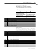
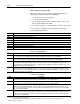
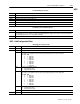
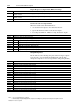
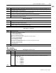
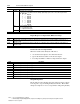
Table Of Contents
- 1771-6.5.88, Plastic Molding Module Reference Manual
- Summary of Changes
- Table of Contents
- Preface
- 1 - Abbreviated Command and Status Blocks
- Chapter Contents
- CLC - Clamp and Eject ERC Values Block
- CPC - Clamp Close Profile Block
- DYC - Dynamic Command Block
- EAC - Ejector Advance Configuration Block
- EPC - Ejector Profile Block
- ERC - Ejector Retract Configuration Block
- FCC - First Clamp Close Configuration Block
- FOC - First Clamp Open Configuration Block
- HDC - Hold Configuration Block
- HPC - Pack/Hold Profile Block
- INC - Injection Configuration Block
- IPC - Injection Profile Block
- JGC - Jog Configuration Block
- LPC - Clamp Low Pressure Close Configuration Block
- MCC - Module Configuration Command Block
- OPC - Clamp Open Profile Block
- OSC - Clamp Open Slow Configuration Block
- PKC - Pack Configuration Block
- PLC - Plastication Configuration Block
- PPC - Plastication Profile Block
- PRC - Pre-decompression Configuration Block
- PSC - Post- decompression Configuration Block
- PTC - Process Trace Configuration Block
- RLC - Inject ERC Values Block
- SCC - Second Clamp Close Configuration Block
- SOC - Second Clamp Open Configuration Block
- TCC - Third Clamp Close Configuration Block
- TOC - Third Clamp Open Configuration Block
- CLS - Clamp and Eject ERC Values Status Block
- CPS - Clamp Close Profiles Status Block
- EPS - Ejector Profile Status Block
- HPS - Pack/Hold Profile Status Block
- IPS - Injection Profile Status Block
- OPS - Clamp Open Profiles Status Block
- PPS - Plastication Profile Status Block
- PTS - Process Trace Status Block
- RLS - Inject ERC Values Status Block
- SYS - System Status Block
- 2 - Command Word/Bit Descriptions
- Alphabetical List of Command Blocks and Block ID Codes
- List of Data Words
- Engineering Units
- Data Blocks Require I/O Configuration
- Data Blocks for System Control
- Data Blocks for Controlling Ram (Screw) Position
- Data Blocks for Controlling Clamp Position
- Data Blocks for Controlling Ejector Position
- Sensors Required
- CLC CLC - Clamp and Eject ERC Values Block
- CPC - Clamp Close Profile Block
- DYC DYC - Dynamic Command Block
- EAC - Ejector Advance Configuration Block
- EPC - Ejector Profile Block
- ERC - Ejector Retract Configuration Block
- FCC - First Clamp Close Configuration Block
- FOC - First Clamp Open Configuration Block
- HDC - Hold Configuration Block
- HPC - Pack/Hold Profile Block
- INC - Injection Configuration Block
- IPC - Injection Profile Block
- JGC - Jog Configuration Block
- LPC - Clamp Low Pressure Close Configuration Block
- MCC - Module Configuration Command Block
- OPC - Clamp Open Profile Block
- OSC - Clamp Open Slow Configuration Block
- PKC - Pack Configuration Block
- PLC Plastication Configuration Command Block (PLC)
- PPC - Plastication Profile Block
- PRC - Pre-decompression Configuration Block
- PSC - Post-decompression Configuration Block
- PTC - Process Trace Configuration Block
- RLC - Inject ERC Values Block
- SCC - Second Clamp Close Configuration Block
- SOC - Second Clamp Open Configuration Block
- TCC - Third Clamp Close Configuration Block
- TOC - Third Clamp Open Configuration Block
- 3 - Word/Bit Descriptions
- List of Status Blocks and Block ID Codes
- List of Data Words
- Data Blocks Require I/O Configuration
- Engineering Units
- Status Block for Reporting System Status
- Status Blocks for Reporting Ram (Screw) Position
- Status Blocks for Reporting Clamp Position
- Status Blocks for Reporting Ejector Position
- CLS - Clamp and Eject ERC Values Status Block
- CPS - Clamp Close Profiles Status Block
- EPS - Ejector Profile Status Block
- HPS - Pack/Hold Profile Status Block
- IPS ú Injection Profile Status Block
- OPS - Clamp Open Profiles Status Block
- PPS - Plastication Profile Status Block
- PTS - Process Trace Status Block
- RLS - Inject ERC Values Status Block
- SYS - System Status Block
- 4 - Programming Error Codes
- 5 - Module Specifications
- 6 - Calibration Instructions
- A - Single transfer for Reporting Ejector Status
- Back cover
2–54 Command Word/Bit Descriptions
Publication
1771-6.5.88 – July 1997
Notes: 1. For [ ] engineering units, see page 3.
2. When using the Inject/Clamp/Eject mode, all pressure readings are system pressure at input 2, except where noted.
Word DescriptionBit
B04-B06 Selected Pressure Control Valve
The module uses its algorithm to drive the following output during any Press/Pos or Press/Time Injection Profile.
B06 B05 B04
0 0 0 Output #1
0 0 1 Output #2
0 1 0 Output #3
0 1 1 Output #4
1 0 0 Output #5
1 0 1 Output #6
1 1 0 Output #7
1 1 1 Output #8
B07 Pressure Algorithm Selection
= 0 Dependent Gains (ISA)
= 1 Independent Gains (A-B)
B08-B15 Open
INC03 - 04 Open
Expert Response Compensation (ERC) Percentage
Word Description
INC05 Minimum Velocity Control ERC Percentage [31] Although error coding allows range of 00000 to 09999, the module limits it to a
minimum of 01000.
INC06 Minimum Pressure Control ERC Percentage [31] Although error coding allows range of 00000 to 09999, the module limits it to a
minimum of 01000.
INC07, 08 Open
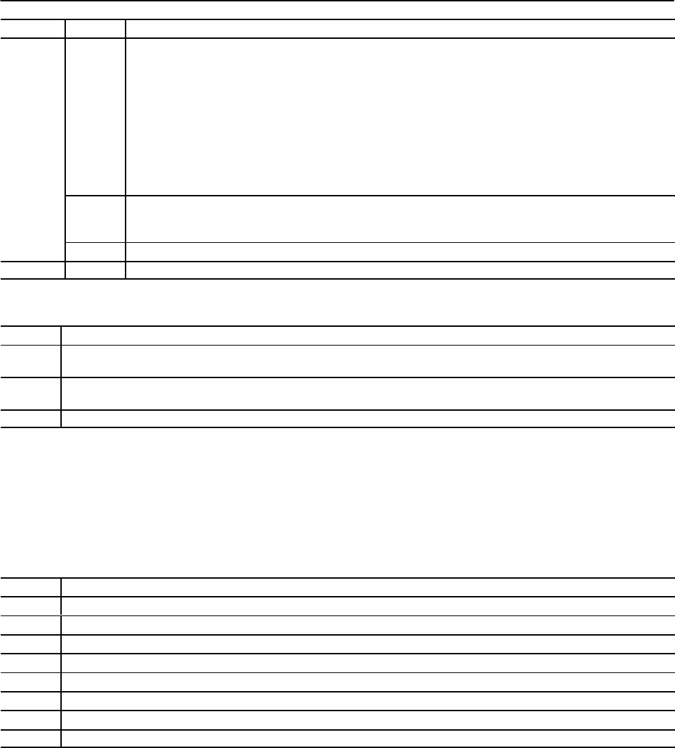
Unselected Valve Set-output Values
When the module starts the Injection Profile, it:
• sets its unselected outputs to the values listed below
• ignores the unselected value of the selected output
• uses ramp rates INC17 - INC32 to ramp unselected outputs
Word Description
INC09 Output #1 Set-output Value during Profile [19]
INC10 Output #2 Set-output Value during Profile [19]
INC11 Output #3 Set-output Value during Profile [19]
INC12 Output #4 Set-output Value during Profile [19]
INC13 Output #5 Set-output Value during Profile [19]
INC14 Output #6 Set-output Value during Profile [19]
INC15 Output #7 Set-output Value during Profile [19]
INC16 Output #8 Set-output Value during Profile [19]
Output Ramp Rates
The module uses the following ramp rates when moving its outputs
from setpoint to setpoint during the Injection Profile. The module
interprets a ramp rate of zero as a step function ramp (ramp disable).