
User Manual

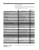
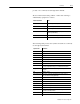
Table Of Contents
- 1771-6.5.88, Plastic Molding Module Reference Manual
- Summary of Changes
- Table of Contents
- Preface
- 1 - Abbreviated Command and Status Blocks
- Chapter Contents
- CLC - Clamp and Eject ERC Values Block
- CPC - Clamp Close Profile Block
- DYC - Dynamic Command Block
- EAC - Ejector Advance Configuration Block
- EPC - Ejector Profile Block
- ERC - Ejector Retract Configuration Block
- FCC - First Clamp Close Configuration Block
- FOC - First Clamp Open Configuration Block
- HDC - Hold Configuration Block
- HPC - Pack/Hold Profile Block
- INC - Injection Configuration Block
- IPC - Injection Profile Block
- JGC - Jog Configuration Block
- LPC - Clamp Low Pressure Close Configuration Block
- MCC - Module Configuration Command Block
- OPC - Clamp Open Profile Block
- OSC - Clamp Open Slow Configuration Block
- PKC - Pack Configuration Block
- PLC - Plastication Configuration Block
- PPC - Plastication Profile Block
- PRC - Pre-decompression Configuration Block
- PSC - Post- decompression Configuration Block
- PTC - Process Trace Configuration Block
- RLC - Inject ERC Values Block
- SCC - Second Clamp Close Configuration Block
- SOC - Second Clamp Open Configuration Block
- TCC - Third Clamp Close Configuration Block
- TOC - Third Clamp Open Configuration Block
- CLS - Clamp and Eject ERC Values Status Block
- CPS - Clamp Close Profiles Status Block
- EPS - Ejector Profile Status Block
- HPS - Pack/Hold Profile Status Block
- IPS - Injection Profile Status Block
- OPS - Clamp Open Profiles Status Block
- PPS - Plastication Profile Status Block
- PTS - Process Trace Status Block
- RLS - Inject ERC Values Status Block
- SYS - System Status Block
- 2 - Command Word/Bit Descriptions
- Alphabetical List of Command Blocks and Block ID Codes
- List of Data Words
- Engineering Units
- Data Blocks Require I/O Configuration
- Data Blocks for System Control
- Data Blocks for Controlling Ram (Screw) Position
- Data Blocks for Controlling Clamp Position
- Data Blocks for Controlling Ejector Position
- Sensors Required
- CLC CLC - Clamp and Eject ERC Values Block
- CPC - Clamp Close Profile Block
- DYC DYC - Dynamic Command Block
- EAC - Ejector Advance Configuration Block
- EPC - Ejector Profile Block
- ERC - Ejector Retract Configuration Block
- FCC - First Clamp Close Configuration Block
- FOC - First Clamp Open Configuration Block
- HDC - Hold Configuration Block
- HPC - Pack/Hold Profile Block
- INC - Injection Configuration Block
- IPC - Injection Profile Block
- JGC - Jog Configuration Block
- LPC - Clamp Low Pressure Close Configuration Block
- MCC - Module Configuration Command Block
- OPC - Clamp Open Profile Block
- OSC - Clamp Open Slow Configuration Block
- PKC - Pack Configuration Block
- PLC Plastication Configuration Command Block (PLC)
- PPC - Plastication Profile Block
- PRC - Pre-decompression Configuration Block
- PSC - Post-decompression Configuration Block
- PTC - Process Trace Configuration Block
- RLC - Inject ERC Values Block
- SCC - Second Clamp Close Configuration Block
- SOC - Second Clamp Open Configuration Block
- TCC - Third Clamp Close Configuration Block
- TOC - Third Clamp Open Configuration Block
- 3 - Word/Bit Descriptions
- List of Status Blocks and Block ID Codes
- List of Data Words
- Data Blocks Require I/O Configuration
- Engineering Units
- Status Block for Reporting System Status
- Status Blocks for Reporting Ram (Screw) Position
- Status Blocks for Reporting Clamp Position
- Status Blocks for Reporting Ejector Position
- CLS - Clamp and Eject ERC Values Status Block
- CPS - Clamp Close Profiles Status Block
- EPS - Ejector Profile Status Block
- HPS - Pack/Hold Profile Status Block
- IPS ú Injection Profile Status Block
- OPS - Clamp Open Profiles Status Block
- PPS - Plastication Profile Status Block
- PTS - Process Trace Status Block
- RLS - Inject ERC Values Status Block
- SYS - System Status Block
- 4 - Programming Error Codes
- 5 - Module Specifications
- 6 - Calibration Instructions
- A - Single transfer for Reporting Ejector Status
- Back cover

Table of Contents
x
ID
= 15 – PPC – Plastication Profile Block
4–33
. . . . . . . . . . . . . .
ID = 16 – PSC – Post-Decompression Configuration Block
4–38
. .
ID
= 17 – FOC – First Clamp Open Configuration Block
4–39
. . . .
ID
= 18 – SOC – Second Clamp Open Configuration Block
4–40
. .
ID
= 19 – T
OC – Third Clamp Open Configuration Block
4–42
. . . .
ID
= 20 – OSC – Clamp Open Slow Configuration Block
4–43
. . . .
ID
= 21 – OPC – Clamp Open Profile Block
4–44
. . . . . . . . . . . . .
ID
= 22 – EAC – Ejector Advance Configuration Block
4–50
. . . . .
ID
= 23 – ERC – Ejector Retract Configuration Block
4–51
. . . . . .
ID
= 24 – EPC – Ejector Profile Block
4–52
. . . . . . . . . . . . . . . . .
ID = 25 – DYC – Dynamic Command Block
4–55
. . . . . . . . . . . . .
ID
= 26 – RLC – Inject ERC V
alues Block
4–56
. . . . . . . . . . . . . .
ID
= 27 – CLC– Clamp and Eject ERC V
alues Block
4–57
. . . . . . .
ID = 28 – PTC – Process T
race Configuration Block
4–57
. . . . . . .
Notes:
4–58
. . . . . . . . . . . . . . . . . . . . . . . . . . . . . . . . . . . . . . . .
Module Specifications
5–1. . . . . . . . . . . . . . . . . . . . . . . .
I/O
Specifications
5–1
. . . . . . . . . . . . . . . . . . . . . . . . . . . . . . . .
Environmental
Conditions
5–1
. . . . . . . . . . . . . . . . . . . . . . . . . .
Hardware Requirements
5–1
. . . . . . . . . . . . . . . . . . . . . . . . . . .
Process
Control Options
5–2
. . . . . . . . . . . . . . . . . . . . . . . . . .
Calibration Instructions
6–1. . . . . . . . . . . . . . . . . . . . . . .
Calibration
Equipment Required
6–1
. . . . . . . . . . . . . . . . . . . . .
About
This Procedure
6–1
. . . . . . . . . . . . . . . . . . . . . . . . . . . .
Map Your BTW and BTR Data Blocks
6–2
. . . . . . . . . . . . . . . . .
Write Y
our Calibration Logic
6–2
. . . . . . . . . . . . . . . . . . . . . . . .
Set Internal Jumpers
6–3
. . . . . . . . . . . . . . . . . . . . . . . . . . . . .
Wire the Wiring Arms
6–5
. . . . . . . . . . . . . . . . . . . . . . . . . . . . .
Input
Wiring
6–5
. . . . . . . . . . . . . . . . . . . . . . . . . . . . . . . . . .
Output
Wiring
6–5
. . . . . . . . . . . . . . . . . . . . . . . . . . . . . . . .
Calibration
Setup Using Optional Equipment
6–6
. . . . . . . . . . . .
Calibration
Setup at the Machine Location
6–6
. . . . . . . . . . . . . .
Calibration
Procedure for Inputs
6–7
. . . . . . . . . . . . . . . . . . . . .
Calibration
Procedure for Outputs
6–8
. . . . . . . . . . . . . . . . . . . .
Notes:
6–10
. . . . . . . . . . . . . . . . . . . . . . . . . . . . . . . . . . . . . . . .
Single-transfer for Reporting Ejector Status
A–1. . . . . . .
How
the Enhancement Ef
fects System Operation
A–1
. . . . . . . . .
Notes:
A–2
. . . . . . . . . . . . . . . . . . . . . . . . . . . . . . . . . . . . . . . .