
User Manual
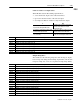
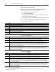
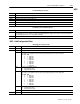
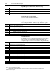
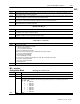
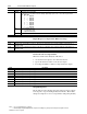
Table Of Contents
- 1771-6.5.88, Plastic Molding Module Reference Manual
- Summary of Changes
- Table of Contents
- Preface
- 1 - Abbreviated Command and Status Blocks
- Chapter Contents
- CLC - Clamp and Eject ERC Values Block
- CPC - Clamp Close Profile Block
- DYC - Dynamic Command Block
- EAC - Ejector Advance Configuration Block
- EPC - Ejector Profile Block
- ERC - Ejector Retract Configuration Block
- FCC - First Clamp Close Configuration Block
- FOC - First Clamp Open Configuration Block
- HDC - Hold Configuration Block
- HPC - Pack/Hold Profile Block
- INC - Injection Configuration Block
- IPC - Injection Profile Block
- JGC - Jog Configuration Block
- LPC - Clamp Low Pressure Close Configuration Block
- MCC - Module Configuration Command Block
- OPC - Clamp Open Profile Block
- OSC - Clamp Open Slow Configuration Block
- PKC - Pack Configuration Block
- PLC - Plastication Configuration Block
- PPC - Plastication Profile Block
- PRC - Pre-decompression Configuration Block
- PSC - Post- decompression Configuration Block
- PTC - Process Trace Configuration Block
- RLC - Inject ERC Values Block
- SCC - Second Clamp Close Configuration Block
- SOC - Second Clamp Open Configuration Block
- TCC - Third Clamp Close Configuration Block
- TOC - Third Clamp Open Configuration Block
- CLS - Clamp and Eject ERC Values Status Block
- CPS - Clamp Close Profiles Status Block
- EPS - Ejector Profile Status Block
- HPS - Pack/Hold Profile Status Block
- IPS - Injection Profile Status Block
- OPS - Clamp Open Profiles Status Block
- PPS - Plastication Profile Status Block
- PTS - Process Trace Status Block
- RLS - Inject ERC Values Status Block
- SYS - System Status Block
- 2 - Command Word/Bit Descriptions
- Alphabetical List of Command Blocks and Block ID Codes
- List of Data Words
- Engineering Units
- Data Blocks Require I/O Configuration
- Data Blocks for System Control
- Data Blocks for Controlling Ram (Screw) Position
- Data Blocks for Controlling Clamp Position
- Data Blocks for Controlling Ejector Position
- Sensors Required
- CLC CLC - Clamp and Eject ERC Values Block
- CPC - Clamp Close Profile Block
- DYC DYC - Dynamic Command Block
- EAC - Ejector Advance Configuration Block
- EPC - Ejector Profile Block
- ERC - Ejector Retract Configuration Block
- FCC - First Clamp Close Configuration Block
- FOC - First Clamp Open Configuration Block
- HDC - Hold Configuration Block
- HPC - Pack/Hold Profile Block
- INC - Injection Configuration Block
- IPC - Injection Profile Block
- JGC - Jog Configuration Block
- LPC - Clamp Low Pressure Close Configuration Block
- MCC - Module Configuration Command Block
- OPC - Clamp Open Profile Block
- OSC - Clamp Open Slow Configuration Block
- PKC - Pack Configuration Block
- PLC Plastication Configuration Command Block (PLC)
- PPC - Plastication Profile Block
- PRC - Pre-decompression Configuration Block
- PSC - Post-decompression Configuration Block
- PTC - Process Trace Configuration Block
- RLC - Inject ERC Values Block
- SCC - Second Clamp Close Configuration Block
- SOC - Second Clamp Open Configuration Block
- TCC - Third Clamp Close Configuration Block
- TOC - Third Clamp Open Configuration Block
- 3 - Word/Bit Descriptions
- List of Status Blocks and Block ID Codes
- List of Data Words
- Data Blocks Require I/O Configuration
- Engineering Units
- Status Block for Reporting System Status
- Status Blocks for Reporting Ram (Screw) Position
- Status Blocks for Reporting Clamp Position
- Status Blocks for Reporting Ejector Position
- CLS - Clamp and Eject ERC Values Status Block
- CPS - Clamp Close Profiles Status Block
- EPS - Ejector Profile Status Block
- HPS - Pack/Hold Profile Status Block
- IPS ú Injection Profile Status Block
- OPS - Clamp Open Profiles Status Block
- PPS - Plastication Profile Status Block
- PTS - Process Trace Status Block
- RLS - Inject ERC Values Status Block
- SYS - System Status Block
- 4 - Programming Error Codes
- 5 - Module Specifications
- 6 - Calibration Instructions
- A - Single transfer for Reporting Ejector Status
- Back cover

2–53Command Word/Bit Descriptions
Publication
1771-6.5.88 – July 1997
INC
Word Description
HPC37 Hold Segment 4 Time Setpoint [21] The module controls the selected process pressure to the setpoint HPC35 or HPC36 for this
time period beginning at completion of Segment 3.
HPC38 Hold Segment 5 Cavity Pressure Setpoint [04] If you select Cav Press/Time profile execution, the module controls cavity pressure to
this setpoint at completion of segment 4 for time period specified by HPC40.
HPC39 Hold Segment 5 Ram (Screw) Pressure Setpoint [01] If you select Ram Press/Time profile execution, the module controls ram
(screw) pressure to this setpoint at completion of segment 4 for time period specified by HPC40.
HPC40 Hold Segment 5 Time Setpoint [21] The module controls the selected process pressure to the setpoint HPC38 or HPC39 for this
time period beginning at completion of Segment 4.
Hold Profile Offsets
Word Description
HPC41 Hold Profile Cavity Pressure Offset [04] If you select Cav Press/Time profile execution, the module applies this entry (after reading
the sign bit) to each cavity pressure profile setpoint.
HPC42 Hold Profile Ram (Screw) Pressure Offset [01] If you select Ram Press/Time profile execution, the module applies this entry (after
reading the sign bit) to each ram (screw) pressure profile setpoint.
HPC43 - 60 Open
Critical Process Setpoints
Word Description
HPC61 Cure Timer Preset [22]
At completion of the Hold Profile, the module:
S
starts an internal Cure Timer
S
sets master status bit SYS03-B03
S
reports the accumulated time in SYS58
When the Cure Timer accumulated value in SYS58 equals this entry, the module:
S
resets master status bit SYS03-B03
S
sets master status bit SYS03-B05
S
stops accumulating time in SYS58
If it receives an F-to-T transition of DYC02-B00, -B01, -B02, -B03 or DYC03-B01, the module:
S
resets master status bit SYS03-B03
S
resets master status bit SYS03-B05
S
resets SYS58 to zero
HPC62 - 64 Open
Bit-mapped Control Words
Word Bit Description
INC01 Block ID = 00001000 (Low byte). High byte reserved for the module. Do not use.
INC02 Configuration Selections
B00-B02 Selected Velocity Control Valve
The module uses its algorithm to drive the following output during any Vel/Pos or LimVel/Pos Injection Profile.
B02 B01 B00
0 0 0 Output #1
0 0 1 Output #2
0 1 0 Output #3
0 1 1 Output #4
1 0 0 Output #5
1 0 1 Output #6
1 1 0 Output #7
1 1 1 Output #8
INC02 B03 Open
INC – Injection
Configuration Block