
User guide


Configure the QDC Module's I/O
Chapter 3
3-17
Configure Digital Filters for Position Inputs
You may enable an optional digital filter on position inputs to reduce
electrical noise from a potentiometer-type position sensors or picked up by
your input circuits.
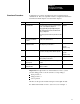
To determine if you need a digital filter, move the ram (screw), clamp,
and/or ejector very slowly. With your programming terminal, look for
erratic position numbers reported for ram (screw), clamp, and/or ejector
position by examining these words:
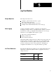
For this Input: In Word: Look at this ProSet 600 Address:
Ram (Screw) SYS25 N40:177
Clamp SYS27 N40:179
Ejector SYS28 N40:180
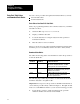
To determine the time constant (00.10 sec max), start with a small value
such as 00.01. A value of zero disables the filter.
To Filter this Input: In Word: Enter a Filter Time Constant in:
Ram (Screw) MCC16 N40:12
Clamp MCC30 N40:26
Ejector MCC44 N40:40
ATTENTION: Increasing the value of the time constant
decreases the QDC module’s capability to respond quickly to
travel limits and/or to accurately locate programmed positions.
We recommend that you keep the time constant under 00.10.
For example, with a clamp velocity of 2 inches/sec, a 00.01 time constant
allows a 0.20 inch travel before the QDC module can react to a travel limit.
Important: If you have a noisy potentiometer-type position sensor and
digital filtering slows the QDC module’s response time too much, consider
replacing the sensor with a non-contact, linear-displacement type.
Download time constants to the QDC module using the procedures
presented earlier in this chapter.