
User guide

Record
Y
our SWTL Configuration Values Here
Configure the QDC Module's I/O
Chapter 3
3-15
Configure the QDC module for SWTL alarms as follows:
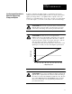
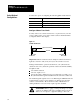
1. Determine these SWTL values for ram (screw), clamp, and/or ejector
travel with respect to the range of physical travel.
SWTL deadband
Maximum SWTL
Minimum SWTL
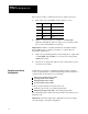
2. Record non-zero SWTL values on Worksheet 3-F. Zero values
disable the corresponding SWTLs.
ATTENTION: Leaving your SWTL settings at zero (MCC13,
14, 27, 28, 41, 42) inhibits the QDC module from performing
this safety function.
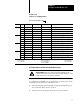
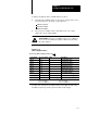
Worksheet 3F
SWTL
Configuration V
alues
Control Word ProSet 600 Addr. Value Description
MCC13 N40:9 Screw Minimum SWTL
1
MCC14 N40:10 Screw Maximum SWTL
1
MCC15 N40:11 10 Screw SWTL Deadband
2
MCC27 N40:23 Clamp Minimum SWTL
1
MCC28 N40:24 Clamp Maximum SWTL
1
MCC29 N40:25 10 Clamp SWTL Deadband
2
MCC41 N40:37 Ejector Minimum SWTL
1
MCC42 N40:38 Ejector Maximum SWTL
1
MCC43 N40:39 10 Ejector SWTL Deadband
2
1
Incremental
distance measured from zero
2
Incremental distance measured as noted
00.00 to 99.99 Inches 00.00 to 99.99 Inches
000.0 to 999.9 Millimeters 000.0 to 999.9 Millimeters
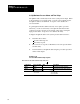
You may now download your adjusted values to the QDC module using
the MCC download procedure presented earlier in this chapter.