
User guide

Record
Y
our Final V
alues Here
Configure the QDC Module's I/O
Chapter 3
3-9
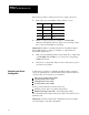
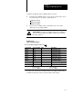
Worksheet 3E
Final Sensorconfiguration V
alues
Input Line Control Word ProSet 600 Addr. Value Description
1 1 MCC09 N40:5 0 Minimum Screw Position
1
2 MCC10 N40:6 Maximum Screw Position
1
3 MCC11 N40:7 Analog Signal @ Min Screw Position
2
4 MCC12 N40:8 Analog Signal @ Max Screw Position
2
2 5 MCC57 N40:53 0 Minimum System Pressure
3
6 MCC58 N40:54 Maximum System Pressure
3
7 MCC59 N40:55 Analog Signal @ Min System Pressure
2
8 MCC60 N40:56 Analog Signal @ Max System Pressure
2
3 9 MCC23 N40:19 0 Minimum Clamp Position
1
10 MCC24 N40:20 Maximum Clamp Position
1
11 MCC25 N40:21 Analog Signal @ Min Clamp Position
2
12 MCC26 N40:22 Analog Signal @ Max Clamp Position
2
4 13 MCC31 N40:27 0 Minimum Ejector Position
1
14 MCC32 N40:28 Maximum Ejector Position
1
15 MCC33 N40:29 Analog Signal @ Min Ejector Position
2
16 MCC34 N40:30 Analog Signal @ Max Ejector Position
2
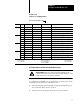
1
Incremental Distance
2
Input Signal Range
3
Pressure
00.00
to 99.99in
00.00 to 10.00VDC or
0000 to 9999 PSI
000.0 to 999.9mm
01.00 to 05.00VDC or
000.0 to 999.9 Bar
04.00 to 20.00MADC
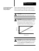
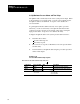
Determine Values for Ram (Screw) Position Sensor
ATTENTION: Incorrect values entered in DYC09-12 may
result in rapid ram (screw) motion and potential damage to your
barrel and seals of your injection cylinder.
To complete the configuration for your ram (screw) position sensor, do the
following and enter the results on Worksheet 3-E:
1. Move the ram (screw) forward until it reaches its mechanical stop at
the nozzle end. This is the zero position.
2. Remove ram (screw) pressure and/or flow to stop movement.