
User guide

Record
Y
our Initial Values Here
Configure the QDC Module's I/O
Chapter 3
3-5
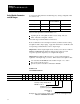
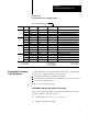
Worksheet 3D
Determine Initial Sensorconfiguration V
alues
Input Line Control Word ProSet
600 Addr
. Value Description
1 1 MCC09 N40:5 0 Minimum Screw Position
1
2 MCC10 N40:6 Maximum Screw Position
1
3 MCC11 N40:7 Analog Signal @ Min Screw Position
2
4 MCC12 N40:8 Analog Signal @ Max Screw Position
2
2 5 MCC57 N40:53 0 Minimum System Pressure
3
6 MCC58 N40:54 Maximum System Pressure
3
7 MCC59 N40:55 Analog Signal @ Min System Pressure
2
8 MCC60 N40:56 Analog Signal @ Max System Pressure
2
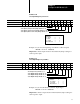
3 9 MCC23 N40:19 0 Minimum Clamp Position
1
10 MCC24 N40:20 Maximum Clamp Position
1
11 MCC25 N40:21 Analog Signal @ Min Clamp Position
2
12 MCC26 N40.22 Analog Signal @ Max Clamp Position
2
4 13 MCC31 N40:27 0 Minimum Ejector Position
1
14 MCC32 N40:28 Maximum Ejector Position
1
15 MCC33 N40:29 Analog Signal @ Min Ejector Position
2
16 MCC34 N40:30 Analog Signal @ Max Ejector Position
2
1
Incremental Distance
2
Input Signal Range
3
Pressure
00.00
to 99.99in
00.00 to 10.00VDC or
0000
to 9999 PSI
000.0
to 999.9mm
01.00 to 05.00VDC or
000.0 to 999.9 Bar
04.00
to 20.00MADC
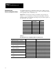
Use this download procedure now and later in this chapter. The procedure
requires you to complete the following general steps:
enter MCC parameters into the PLC-5 data table
download them to the QDC module (with PLC-5 processor in run mode)
correct any programming errors
Next, we describe the general steps.
Enter MCC Parameters into Your PLC5 Data Table
With your programming terminal, enter values from Worksheet 3-A thru
4-D into your PLC-5 data table as follows:
1. Switch the PLC-5 processor to
PROGRAM mode.
2. Display your PLC-5 data table.
Download
MCC Parameters
to the QDC Module