
Manual

Chapter
6
6-1
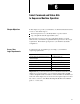
Select Command and Status Bits
to Sequence Machine Operation
In this chapter, we provide you with tables of command and status bits that
you use to write ladder logic to:
monitor input devices on your Ready Panel or operator station
step your QDC module through machine cycles
We suggest how to access your logic requirements and how to use bit
tables to write your machine’s sequential ladder logic based on those logic
requirements. This ladder logic depends on your machine’s hydraulic
configuration.
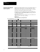
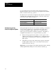
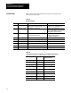
You must add your own ladder logic according to your machine’s
sequencing requirements.
If you need to: Then you must add:
Execute clampopen and clampclose phases
without interruption
no additional ladder logic
Execute the ejector profile without interruption no additional ladder logic
Jog your machine ladder logic (see chapter 5)
Stop at the end of a profile ladder logic to start the next profile
Start a profile on command ladder logic
Stop and notify at the end of the ejector stroke ladder logic to continue the ejector profile
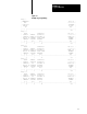
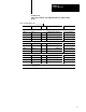
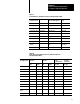
Important: We present information about command and status bits in this
chapter. For your convenience, a cross-reference between Pro-Set 600
software and QDC module bit addresses is listed in Table 6.I and Table 6.J
at the end of this chapter. If you need a more thorough description of these
bits, refer to section 3 of the Plastic Molding Module Reference Manual
(pub. no. 1771-6.5.88).
Chapter
Objectives
Assess Y
our
Logic Requirements