
Manual

Configure the QDC Module's
Inputs and Outputs
Chapter 3
3-5
To determine initial sensor configuration values, refer to Table 3.A, and to
the specifications that accompanied your sensors, valves, and cylinders.
Write down applicable values on Worksheet 3-D.
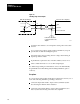
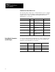
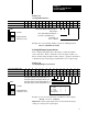
Important: You must enter floating-point numbers and percentages as
integers, so we recommend that you write them in Worksheet 3-D in the
following format: Use an assumed decimal point position that depends on
the range value. For example:
If the Range is: And You Want to
Enter this Value:
Use this
Format:
0 099.99% 75% 07500
0 99.99 inch 7.32 inch 00732
0 0999.9 mm 432.6 mm 4326
4.00 020.00 mA 16mA 01600
0 010.00 vdc 5.6 vdc 00560
0 009.99 sec 0.47 sec 00047
0 09999 PSI 321 PSI 00321
0 0999.9 Bar 222 Bar 2220
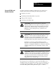
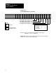
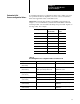
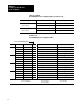
Table 3.A
Determining
Initial Sensorconfiguration V
alues for W
orksheet 3D
Category: If: Then Use a Value Equal to:
Minimum Position
(Lines 1 and 9)
N/A zero
Maximum Position
(Lines 2 and 10)
the
mold is fully closed, the
position is zero
and the ejector retract position is zero
full travel of the sensor
Analog Signal @ Min Position your sensors are forwardacting low end of your selected range
(Line 3 and 11) your sensors are reverseacting high end of your selected range
Analog Signal @ Max Position your sensors are forwardacting high end of your selected range
(Line 4 and 12) your sensors are reverseacting low end of your selected range
Minimum Pressure
(Lines 5 and 13)
N/A minimum range value specified by the
manufacturer
Maximum Pressure
(Lines 6 and 14)
N/A maximum range value specified by the
manufacturer
Determine
Initial
Sensorconfiguration Values