
Manual

Configure the QDC Module's
Inputs and Outputs
Chapter 3
3-2
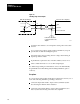
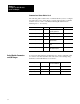
Command and Status Blocks Used
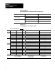
The following table contains a list of command blocks you are to configure
throughout the course of this chapter. You may reference these command
blocks in sections 1 and 3 of the Plastic Molding Module Reference
Manual (pub. no. 1771-6.5.88).
Block: Type: Use in this Chapter: ProSet 600 Files:
Module Configuration (MCC) Command Configure Module I/O
operating parameters
B35
Module Configuration (MCC) Command Select Input Ranges for I/O B35
Module Configuration (MCC) Command Select Output Ranges for I/O B35
Module Configuration (MCC) Command Determine Initial Sensor Con
figuration values
N41
Module Configuration (MCC) Command Determine Software Travel
Limits
N41
Module Configuration (MCC) Command Enter Pressurealarm and
Timedelay Setpoints
N41
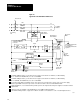
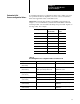
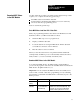
You select module parameters and I/O ranges by setting configuration bits
in control words. First determine and write down correct settings using
Worksheet 3-A thru Worksheet 3-C as follows:
To Configure: In Control Word: Starting At
ProSet 600 Address:
Use this Worksheet:
Module Parameters MCC02 B35/528 Worksheet 3-A
Input Range MCC03 B35/544 Worksheet 3-B
Output Range MCC04 B35/560 Worksheet 3-C
Select
Module Parameters
and I/O Ranges