
Manual

Chapter
2
2-1
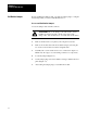
Install the QDC Module
This chapter guides you through the process of installing your QDC
module to assure reliable, safe performance. Major topics described in this
chapter include how to:
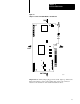
set module jumpers
key your I/O rack
install your module
wire I/O devices to your module
ground your system
plan for E-STOPs and Machine Interlocks
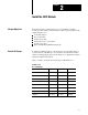
To match your QDC module to your I/O devices, record the I/O ranges of
your I/O devices on Worksheet 2-A. You will use this information in this
chapter for setting jumper plugs, and in chapter 3 to configure the module’s
inputs and outputs with software.
Circle or check your selections for I/O ranges on Worksheet 2-A.
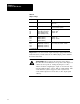
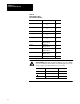
Worksheet 2A
Record
I/O Ranges
I/O Connection: Voltage 1: Voltage 2: Current:
Input 1 (Ejector position) 0 to 10V dc 1 to 5V dc 4 to 20 mA
Input 2 (Ejector pressure) 0 to 10V dc 1 to 5V dc 4 to 20 mA
Input 3 (Clamp position) 0 to 10V dc 1 to 5V dc 4 to 20 mA
Input 4 (Clamp pressure) 0 to 10V dc 1 to 5V dc 4 to 20 mA
Output 1 10 to 10V dc 0 to 10V dc 4 to 20 mA
Output 2 10 to 10V dc 0 to 10V dc 4 to 20 mA
Output 3 10 to 10V dc 0 to 10V dc 4 to 20 mA
Output 4 10 to 10V dc 0 to 10V dc 4 to 20 mA
Chapter
Objectives
Record I/O Ranges