
Manual

Load Initial Profile Values for
Machine Tuning
Chapter 8
8-17
If the QDC module has control of all the valves in your ejector
circuit that are required to change the direction of ejector travel,
select 0 for bit 12 (the QDC module has the control capability during
the Ejector Profile to initiate each subsequent retract/advance stroke
upon completion of the preceding advance/retract stroke). Your PLC
ladder logic needs only to toggle DYC02-B14 (Pro-Set 600 address
B35/414) in order to command the QDC module to execute the entire
Ejector Profile. An example of this configuration is when the
direction of ejector travel is determined by a bi-directional flow
valve connected to the QDC module.
If the QDC module does not have control of all of the valves in your
ejector circuit that are required to change the direction of ejector
travel, select 1 for bit 12 (the QDC module does not have the control
capability during the Ejector Profile to initiate each subsequent
retract/advance stroke upon completion of the preceding
advance/retract stroke). Your PLC ladder logic has to operate the
ejector directional valves not connected to the QDC module in order
to “assist” the QDC module in its execution of the Ejector Profile.
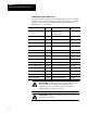
The following is a partial list of the interactive command and status
bits that are provided to program a “Stop-and-Notify” Ejector Profile
in your PLC ladder logic.
Control Word: ProSet 600 address: Performs this action:
DYC02B14 B35/414 Execute Ejector Profile
DYC03B15 B35/431 Continue Ejector Profile
SYS03B08 B35/40 Ejector Profile Stopped at Endof Stroke
SYS03B10 B35/42 Ejector Forward Dwell Timer timing
SYS21B14 B35/334 Ejector Profile in Progress
SYS22B14 B35/350 Ejector Endof Advance setoutput in Progress
SYS22B15 B35/351 Ejector Endof Retract setoutput in Progress
Refer to chapter 6 in this manual for additional information on this
type of ladder logic programming.
An example of the “Stop-and-Notify” configuration is when
direction of ejector travel is determined by discrete solenoid valves
connected to PLC outputs.
At this time, make the selection for bit 12 required by your ejector
hydraulic configuration.