
Manual

Algorithm
0 = Vel/Pos
1 = Press/Pos
Logical Bridge
0 = Start Profile on Clamp Position During Open
1 = Start Profile on Command
Stop and Notify
0 = Ejector Profile to Run without Interruption
1 = QDC to StopandNotify" at end of Stroke
Ejector Tip Strokes
0 = All Strokes to be Full Strokes
1 = Intermediate Strokes to be Tip Strokes
EPC
Block Identifier
Expert Response Compensation
0 = ON
1 = OFF
bit 09 = Press/Pos
bit 08 = Vel/Pos
Open/Closed Loop Selection
0 = Closed Loop
1 = Open Loop
bit 01 = Press/Pos
bit 00 = Vel/Pos
Forward Dwell
0=Apply Forward Dwell on Final Stroke
1=Apply Forward Dwell on Initial Stroke
Velocity Units
0 = Percent Velocity
1 = Inches (mm)/Second
Ejector Profile
0 = Ejector profile enabled
1 = Ejector profile disabled
Code:
Your value
Required initial value
loaded by ProSet 600
0
or 1
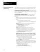
Load Initial Profile Values for
Machine Tuning
Chapter 8
8-14
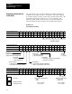
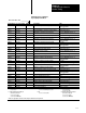
The following two pages contain worksheets for the Ejector Profile (one
worksheet for bit entries and one for word entries). The valve spanning
procedure in chapter 9 requires specific values in certain block entries. We
have already entered those values for you on your worksheets. All
parameters which require an entry based on your specific machine are
discussed briefly below the worksheet, and in detail in later chapters.
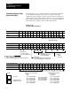
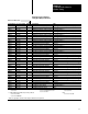
Worksheet 8C
Ejector
(EPC) Profile Block
Control Word EPC01Bxx
15 14 13 12 11 10 09 08 07 06 05 04 03 02 01 00
ProSet 600 Addr. B39/bit
143 142 141 140 139 138 137 136 135 134 133 132 131 130 129 128
Value 0 0 0 0 0 0 0 0 0 0 0 1 1 0 0 0
Control Word EPC03Bxx
15 14 13 12 11 10 09 08 07 06 05 04 03 02 01 00
ProSet 600 Addr. B39/bit
175 174 173 172 171 170 169 168 167 166 165 164 163 162 161 160
Value 0 1 0 * 0 0 0 1 0 0 0 0 0 0 0 1
Control Word EPC04Bxx
15 14 13 12 11 10 09 08 07 06 05 04 03 02 01 00
ProSet 600 Addr. B39/bit
191 190 189 188 187 186 185 184 183 182 181 180 179 178 177 176
Value 0 0 0 0 0 0 1 1 0 0 0 0 0 0 1 1
Determine and Enter Ejector
Profile (EPC)