
Manual


Load Initial Configuration Values
Chapter 7
7-24
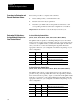
Follow this procedure to complete each worksheet.
1. Decide which profiles you will and will not use.
2. Read the text for the subject parameter.
3. Determine your initial value for that parameter and add it to each
corresponding worksheet at the listed configuration word address.
Important: Block identifier codes are already recorded for you.
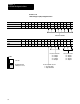
Selected Velocity Control Valve
(FCC02,
SCC02, TCC02, FOC02, SOC02, TOC02, OSC02, EAC02, ERC02)
The QDC module is capable of controlling clamp and ejector movement
using a velocity versus position algorithm. Since up to four valves may be
connected to your QDC module, you must inform the QDC module what
valve you want it to control when utilizing this algorithm. Enter the
appropriate values into your configuration worksheets depending on your
valve configuration.
B02 B01 B00 Selects:
0 0 0 Output #1 Used for Velocity Control
0 0 1 Output #2 Used for Velocity Control
0 1 0 Output #3 Used for Velocity Control
0 1 1 Output #4 Used for Velocity Control
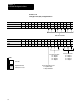
Selected Pressure Control Valve
(FCC02,
SCC02, TCC02, LPC02, FOC02, SOC02, TOC02, OSC02, EAC02, ERC02)
The QDC module can also control clamp and ejector movement using a
pressure versus position algorithm (This is the only algorithm possible in
the Low Pressure Close profile). Again, you must inform the QDC module
what valve you want it to control when utilizing this algorithm. Enter the
appropriate values into your configuration worksheets depending on your
valve configuration.
B06 B05 B04 Selects:
0 0 0 Output #1 Used for Pressure Control
0 0 1 Output #2 Used for Pressure Control
0 1 0 Output #3 Used for Pressure Control
0 1 1 Output #4 Used for Pressure Control
Procedure to Determine and
Record W
orksheet V
alues
Determine Bit Selections:
Assign Module Outputs for
Your Control Valves