
User Manual

Enter
Y
our Initial Values Here
Jog Your Machine
Chapter 5
5-8
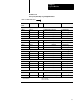
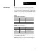
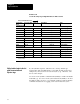
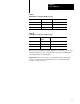
Worksheet 5. B
Screwrotate & Eject Jog Configuration Values for Indirect Control
Control Block
Word
ProSet 600 Addr. Value Description Units
Screw Rotate Jog
JGC09 N40:65 Set Output Values Output #1 % Signal Output
1
JGC10 N40:66 Output #2 % Signal Output
1
JGC11 N40:67 Output #3 % Signal Output
1
JGC12 N40:68 Output #4 % Signal Output
1
Ejector, Advance Jog
JGC49 N40:105 Set Output Values Output #1 % Signal Output
1
JGC50 N40:106 Output #2 % Signal Output
1
JGC51 N40:107 Output #3 % Signal Output
1
JGC52 N40:108 Output #4 % Signal Output
1
Ejector, Retract Jog
JGC57 N40:113 Set Output Values Output #1 % Signal Output
1
JGC58 N40:114 Output #2 % Signal Output
1
JGC59 N40:115 Output #3 % Signal Output
1
JGC60 N40:116 Output #4 % Signal Output
1
1
%
Signal Output
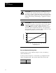
00.00 to 99.99 %
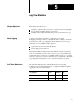
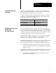
If your hydraulics require it, take time now to develop ladder logic
(independent of Pro-Set 600 software) so the QDC module (in inject and
clamp mode) can assist in screw-rotate and ejector jogs. Otherwise, omit
the rest of this chapter.
Use word 1 in the dynamic command block (DYC01) to enable and disable
individual jogs. Use word 1 in the system status block (SYS01) to monitor
the QDC module’s reaction to jog commands. Tables 5.C and 5.D identify
command and status bits for jogging screw rotation and/or the ejector.
Write Ladder Logic to Assist
with Screwrotate and
Ejector Jogs