
User Manual

Jog Your Machine
Chapter 5
5-5
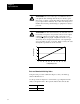
Take time now to develop ladder logic (independent of Pro-Set 600
software) to jog the ram (screw) and clamp. You need to monitor switches
on your operator control panel, and set corresponding command bits.
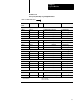
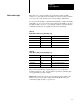
Use word 1 in the dynamic command block (DYC01) to enable and disable
individual jogs. Use word 1 in the system status block (SYS01) to monitor
the QDC module’s reaction to jog commands. Tables 5.A and 5.B identify
command and status bits for jogging the ram (screw) and clamp.
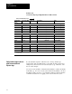
Table 5.A
Enable
Bits for Ram (Screw) and Clamp Jogs
Control Block Word: ProSet 600 Address: Description:
DYC01B10 B34/394 Execute Ram (Screw) Jog Forward
DYC01B11 B34/395 Execute Ram (Screw) Jog Reverse
DYC01B12 B34/396 Execute Clamp Jog Forward
DYC01B13 B34/397 Execute Clamp Jog Reverse
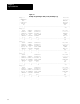
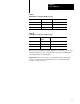
Table 5.B
Status
Bits for Ram (Screw) and Clamp Jogs
Status Block Word: ProSet 600 Address: Description:
SYS01B10 B34/10 Ram (Screw) Jog Forward in Progress
SYS01B11 B34/11 Ram (Screw) Jog Reverse in Progress
SYS01B12 B34/12 Clamp Jog Forward in Progress
SYS01B13 B34/13 Clamp Jog Reverse in Progress
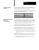
We provide a programming example (Figure 5.1) of jog control for
instructional purposes only. Your application-specific programming may
vary significantly from this example.
Important: You may also need to develop ladder logic that changes the
direction of ram (screw) and/or clamp travel hydraulically when you
command the QDC module to jog in reverse.
Write Ladder Logic