
User Manual


Overview of Remaining
Configuration Procedures
Chapter 4
4-3
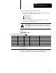
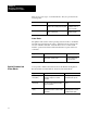
Configuration procedures detailed over the next several chapters are
outlined below. The procedures are sequential in nature: configuration
information determined in initial chapters is needed in later chapters.
Step: Procedure: Enter this Information: Refer to:
1 Jog Your Machine Machine jog pressure and flow setpoints are
entered into the Jog Configuration (JGC) block.
You actually jog your inject and clamp with
commands in the Dynamic Command Block (DYC)
to further refine your jog configuration.
Jog pressure alarm setpoints are configured.
Chapter 5
2 Write a PLC5 Program to
Coordinate Phases
The QDC module offers many machine operation
options to meet nearly any injection molding
machine's requirements.
PLC5 ladder logic is required to cycle the machine
in the desired manner.
Chapter 6
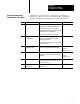
3 Enter Initial
Configuration Values
Valves/Outputs responsible for controlling pressure
or flow, valve spanning values and ramp rates.
Chapter 7
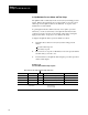
(Used in
Chapters 9 & 10)
4 Enter Initial Profile Values Initial machine operation setpoints (pressure,
velocity, position, time setpoints, other partspecific
information)
Chapter 8
(Used in
Chapters 9 & 10)
5 Span your Valves Configuration parameters necessary to accurately
span your inject and clamp valves. You also set
profile pressure alarms.
Chapter 9
6 Tune your Machine for
Producing Parts
Topics to consider when machine and part tuning
are discussed.
Chapter 10
Overview of Remaining
Configuration Procedures