
User Manual


Enter
Y
our Pressurealarm and T
imedelay Values Here
Configure the QDC Module's I/O
Chapter 3
3-16
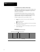
Set Up Maximum Pressure Alarms and Time Delays
The QDC module continuously monitors ram (screw) and clamp pressure
inputs. When it detects that the process input equals or exceeds a preset
alarm setpoint, the QDC module sets an alarm bit. A setpoint of zero
disables the associated alarm.
To guard against nuisance alarms caused by noise spikes or pressure
transients, you can set a time delay so the QDC module must monitor
continuous excessive pressure for an amount of time before setting the
high pressure alarm. A setpoint of zero disables this delay.
Configure the QDC module for pressure alarms as follows:
1. Determine these values for ram (screw) and/or clamp pressure
alarms:
pressure-alarm setpoint
time-delay setpoint
2. Record non-zero setpoints on Worksheet 3-G for the pressure alarms
and time delays you want to use.
3. Download them to the QDC module using the procedures presented
earlier in this chapter.
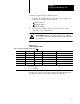
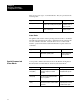
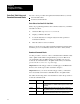
Worksheet 3G
Pressurealarm
and T
imedelay Setpoints
Control Word ProSet 600 Addr. Value Description Units
MCC21 N40:17 Screw Pressurealarm Setpoint Ram (screw) Pressure
2
MCC22 N40:18 Screwpressure Timedelay Setpoint Time
Measured in Seconds
1
MCC35 N40:31 Clamp Pressurealarm Setpoint Clamp Pressure
2
MCC36 N40:32 Clamppressure Timedelay Setpoint Time
Measured in Seconds
1
1
Time
Measured in Seconds
2
Pressure
00.00
to 00.99
0000 to 9999 PSI
000.0 to 999.9 Bar