
User Manual

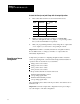
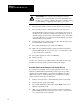

Select
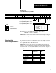
Output 1 Range with bits 01, 00
Select Output 2 Range with bits 03, 02
Select Output 3 Range with bits 05, 04
Select Output 4 Range with bits 07, 06
Output Range
-10 to +10V dc 0 0
0 to +10V dc 0 1
4 to 20 mA 1 0
Not connected 1 1
Code:
Your value
Required initial value
loaded by ProSet 600
0
or 1
Configure the QDC Module's I/O
Chapter 3
3-3
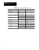
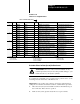
Worksheet 3C
Select Output Ranges for your V
alves
Control W
ord MCC04Bxx
15 14 13 12
11 10
09 08 07 06 05 04 03 02 01 00
ProSet 600 Addr. B34/bit
575 574 573 572 571 570 569 568 567 566 565 564 563 562 561 560
Value 1 1 1 1 1 1 1 1
Example: If you select 0-10V dc for all four output ranges:
MCC04 = 11111111 01010101.
Important: Software output selections must match the jumper settings for
each respective output.
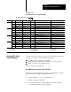
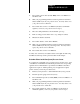
To determine initial sensor configuration values, refer to Table 3.A, and
specifications that accompanied your sensors, valves, and cylinders. Write
down applicable values on Worksheet 3-D.
Important: You must enter floating-point numbers and percentages as
integers, so we recommend that you write them in Worksheet 3-D in the
following format: Use an assumed decimal point position that depends on
the range value. For example:
If the Range is: And You Want to
Enter this Value:
Use this
Format:
0 099.99% 75% 07500
0 99.99 inch 7.32 inch 00732
0 0999.9 mm 432.6 mm 4326
4.00 020.00 mA 16 mA 01600
0 010.00V dc 5.6V dc 00560
0 009.99 sec 0.47 sec 00047
0 09999 psi 321 psi 00321
0 0999.9 Bar 222 Bar 2220
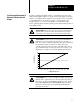
Determine
Initial
Sensorconfiguration Values