
User Manual

Select
System Operation with bits 05 and 04
Inject and Clamp 0 1
Select Singleunit Operation with bit 03 = 1
(0 generates a programming error)
Select English = 0 or
metric = 1 with bit 00
Code:
Your value
Required initial value
loaded by ProSet 600
0
or 1
Select Input 1 (Screw Position) Range with bits 01, 00
Select Input 2 (Screw Pressure) Range with bits 03, 02
Select Input 3 (Clamp Position) Range with bits 05, 04
Select Input 4 (Clamp Pressure) Range with bits 07, 06
Input Range
0 - 10V dc 0 0
1 - 5V dc 0 1
4 - 20 mA 1 0
Not connected 1 1
Code:
Your value
Required initial value
loaded by ProSet 600
0
or 1
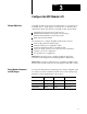
Configure the QDC Module's I/O
Chapter 3
3-2
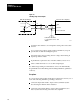
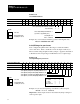
Worksheet 3A
Select Module Parameters
Control W
ord MCC02Bxx
15 14 13 12
11 10
09 08 07 06 05 04 03 02 01 00
ProSet 600 Addr. B34/bit
543 542 541 540 539 538 537 536 535 534 533 532 531 530 529 528
Value 0 0 0 0 0 0 0 0 0 0 0 1 1 0 0
Example: If you select Inject and Clamp operation with English units:
MCC02 = 00000000 00011000
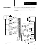
Select I/O Ranges for your Sensors
Next, configure the QDC module’s I/O ranges to match the machine
sensors and valves. Refer to Worksheet 2-A from chapter 2 which you
filled out when setting the QDC module’s jumpers. Apply this information
to Worksheet 3-B for input ranges and Worksheet 3-C for output ranges.
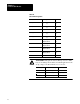
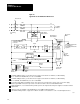
Worksheet 3B
Select
Input Ranges for your Sensors
Control W
ord MCC03Bxx
15 14 13 12
11 10
09 08 07 06 05 04 03 02 01 00
ProSet 600 Addr. B34/bit
559 558 557 556 555 554 553 552 551 550 549 548 547 546 545 544
Value 1 1 1 1 1 1 1 1
Example: If you select an input range of 4-20 mA for all four inputs:
MCC03 = 11111111 10101010.
Important: Software input selections must match the jumper settings for
each respective input.