
User Manual

Install the QDC Module
Chapter 2
2-7
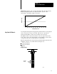
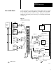
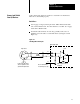
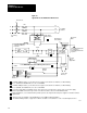
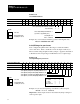
Use the wiring arm (1771-WF) supplied with the QDC module to wire I/O
devices (Figure 2.3). The wiring arm lets you install or remove the QDC
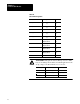
module from the I/O chassis without rewiring. Wiring arm terminals are
numbered in descending order, from the top down, starting with terminal
18 (Table 2.B).
Figure 2.3
I/O
W
iring and Grounding
Customer
PS
Screw
Position
Sensor
Screw
Pressure
Sensor
Clamp
Position
Sensor
Amplifier
Valve 1
Amplifier
Valve 2
Customer
PS
Earth Ground
Input 1
Input 2
Input 3
To Valve 1
To Valve 2
Output 1
Output 2
Wiring Arm
1771WF
+
–
+
–
+
–
+
–
+
–
+
–
+
+
+
–
+
Amplifier
Valve 4
To Valve 4
Output 4
+
–
+
Amplifier
Valve 3
To Valve 3
Output 3
Input 4
+
–
Clamp
Pressure
Sensor
18
17
16
15
14
13
12
11
10
9
8
7
6
5
4
3
2
1
–
+
–
–
–
–
10909I
Wire the QDC Module