
User Manual


Span Your Valves
Chapter 9
9-47
Span your clamp open velocity (flow) valve(s) for optimum velocity
performance. Do this in three parts:
Confirm critical values
Span your clamp open velocity (flow) valve(s)
Test valve linearity
Important: You may omit the next two parts of this section if you have
information on valve spanning. Many injection molding machine OEMs
and hydraulic valve manufacturers provide data on spanning the working
range of valves used on their machines. If this information is available
from your OEM for your machine’s clamp open velocity valve(s), enter the
values into velocity control limits FCC45-48, SCC45-48, TCC45-48, and
OSC45-48 and skip to Span Your Injection Pressure Valve.
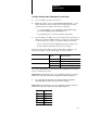
Confirm Critical Values
Important: Confirm that your entries you configuration values (chapter 7)
and profile values (chapter 8) are as follows:
On Worksheet: Confirm Your Configuration: With These Words or Bits: Proset Addr:
7I, 7J, 7K, 7L QDC module output to which you connected
your selected pressure control valve
FOC02B06, B05, B04 = your selection
SOC02B06, B05, B04 = your selection
TOC02B06, B05, B04 = your selection
OSC02B06, B05, B04 = your selection
B37/342, 341, 340
B37/406, 405, 404
B37/470, 469, 468
B37/534, 533, 532
Your unselected setoutput values
for outputs 14
FOC0912 = your value
SOC0912 = your value
TOC0912 = your value
OSC0912 = your value
N43:305308
N43:365368
N43:425428
N43:485488
All ramping is disabled with zero ramp rates FOC1720 = FOC2528 = 0
SOC1720 = SOC2528 = 0
TOC1720 = TOC2528 = 0
OSC1720 = OSC2528 = 0
N43:313316 N43:321324
N43:373376 N43:381384
N43:433436 N43:441444
N43:493496 N43:501504
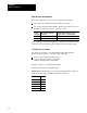
Velocity limits:
Minimum Control Limit
Maximum Control Limit
Selected Velocity Valve, Output for Min
Selected Velocity Valve, Output for Max
FOC45=SOC45=TOC45=OSC45=0
FOC46=SOC46=TOC46=OSC46=sys vel
FOC47=SOC47=TOC47=OSC47=your value
FOC48=SOC48=TOC48=OSC48=your value
N43:341, 401, 461, 521
N43:342, 402, 462, 522
N43:343, 403, 463, 523
N43:344, 404, 464, 524
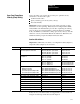
8E Select inches/second for velocity units OPC03B14 = 1 B37/622
Zone overrun - start open slow on overrun OPC03B11 = 0 B37/619
Logical bridge - start next profile OPC03B10 = B09 = B08 = 0 B37/618, 617, 616
Expert Response Compensation (ERC) = Off OPC04B15 - B08 = 1 B37/639632
Openloop control OPC04B07 - B00 = 1 B37/631624
FOC segment velocities OPC09, 12, 15 = your values N43:545, 548, 551
FOC endofsegment position setpoints OPC11, 14, 17 = your values N43:547, 550, 553
Start OSC position setpoint OPC61 = your value N43:597
Mold open position setpoint OPC62 = your value N43:598
If these are not your current values, we suggest that you correct them now
using the download procedure discussed in chapter 4.
Span
Y
our Clamp Open
Velocity (Flow) Valve(s)