
User Manual


Span Your Valves
Chapter 9
9-14
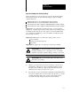
Span your clamp close velocity (flow) valve(s) for optimum velocity
performance. Do this in three parts:
Confirm critical values
Span your clamp close velocity (flow) valve(s)
Test valve linearity with a velocity vs. position profile
Important: You may omit this section if you have the right information on
valve spanning. Many injection molding machine OEMs and hydraulic
valve manufacturers provide data on spanning the working range of valves
used on their machines. If this information is available from your OEM
for your machine’s clamp close velocity valve(s), enter the values into
velocity control limits FCC45-48, SCC45-48, and TCC45-45 and proceed
to Span your Open Slow Valves.
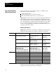
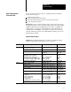
Confirm Critical Values
Important: Confirm that your entries for configuration values (chapter 7)
and profile values (chapter 8) for clamp close profiles are as follows:
On Worksheet: Confirm Your Configuration: With These Words or Bits: ProSet Addr.
7A, 7B, 7C QDC module output to which you connected
your selected velocity control valve
FCC02B02,B01,B00 = your selection
SCC02B02,B01,B00 = your
selection
TCC02B02,B01,B00 = your selection
B37/22, 21, 20
B37/86, 85, 84
B37/150,149,148
Your unselected setoutput values for outputs
14
FCC0912 = your value
SCC0912 = your value
TCC0912 = your value
N43:58
N43:6568
N43:125128
All ramping is disabled with zero ramp rates FCC1720 = FCC2528 = 0
SCC1720 = SCC2528 = 0
TCC1720 = TCC2528 = 0
N43:1316 N43:2124
N43:7376 N43:8184
N43:133136
N43:141144
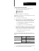
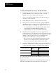
Velocity limits:
Minimum Control Limit
Maximum Control Limit
Selected Velocity Valve, Output for Min
Selected Velocity Valve, Output for Max
FCC45=SCC45=TCC45=0
FCC46=SCC46=TCC46=sys vel
FCC47=SCC47=TCC47=your value
FCC48=SCC48=TCC48=your value
N43:41, 101, 161
N43:42, 102, 162
N43:43, 103, 163
N43:44, 104, 164
8A Selected inches/second as velocity units CPC03B14 = 1 B37/302
Mold protection CPC03B11 = 0 B37/299
Logical bridge CPC03B10 = B09 = B08 = 0 B37/298, 297, 296
Expert Response Compensation (ERC) = Off CPC04B15 = B13B08 = 1 B37/319, 317312
Openloop control CPC04B07 = B05B00 = 1 B37/311, 309304
Endof Segment position setpoints CPC11,14,17 N43:247, 250, 253
Start LPC position CPC61 N43:297
Mold Safe Position CPC62 N43:298
If these are not your current values, we suggest that you correct them now
using the download procedure discussed in chapter 4.
Span
Y
our Clamp Close
Velocity (Flow) Valve(s)