
User Manual

Load Initial Configuration Values
Chapter 7
7-34
Acceleration Ramp Rates
(FCC1720,
SCC1720, TCC1720, LPC1720, INC1720, PKC1720, HDC1720,
PLC1720, FOC1720, SOC1720, TOC1720, OSC1720)
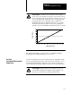
The QDC module uses acceleration ramp rates when moving its outputs to
a higher setpoint during execution of a profile. They affect both selected
and unselected valves. A ramp rate of zero disables ramping, and the QDC
module steps directly from setpoint to setpoint.
We entered zero on corresponding worksheets.
Deceleration Ramp Rates
(FCC2528,
SCC2528, TCC2528, LPC2528, INC2528, PKC2528, HDC2528,
PLC2528, FOC2528, SOC2528, TOC2528, OSC2528)
The QDC module uses deceleration ramp rates when moving its outputs to
a lower setpoint during execution of a profile. They affect selected and
unselected valves alike. A ramp rate of zero disables ramping, and the
QDC module steps directly from setpoint to setpoint.
We entered zero on corresponding worksheets.
Important: The valve spanning procedures in chapter 9 require zero
acceleration and deceleration ramp rates. We help you select the correct
final values required by your application in chapter 10. For additional
information, refer to Section 3 of the Plastic Molding Module Reference
Manual (publication 1771-6.5.88).
EndofProfile Setoutput Values
(FCC3336,
SCC3336, TCC3336, LPC3336, HDC3336, PLC3336, FOC3336,
SOC3336, TOC3336, OSC3336)
The QDC module sets its outputs to these values every time it completes
the appropriate profile when commanded NOT to “bridge” to the next
profile or movement. Set-outputs remain in effect until the QDC module is
commanded to start the next programmed profile (or movement) or is
stopped using stop command DYC02-B15.
Enter values that correspond to zero pressure or zero flow on worksheets.
For assistance in determining your set-output values, refer to Table 7-A.
Important: The valve spanning procedures in chapter 9 require no flow or
pressure after profile execution. We help you select the correct final values
required by your application in chapter 10. For additional information,
refer to Section 3 of the Plastic Molding Module Reference Manual
(publication 1771-6.5.88).
Determine Setoutput Values
for End of Profiles