
Instruction Manual


Enter
Y
our Initial Values Here
Jog Your Machine
Chapter 5
5-3
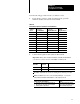
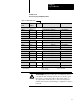
Worksheet 5. A
Ram (screw) Jog Configuration V
alues
Control Block
Word
ProSet 600
Address
Value Description Units
Inject, Forward Jog
JGC17 N40:73 Set Output Values Output #1 % Signal Output
1
JGC18 N40:74 Output #2 % Signal Output
1
JGC19 N40:75 Output #3 % Signal Output
1
JGC20 N40:76 Output #4 % Signal Output
1
Inject, Reverse Jog
JGC25 N40:81 Set Output Values Output #1 % Signal Output
1
JGC26 N40:82 Output #2 % Signal Output
1
JGC27 N40:83 Output #3 % Signal Output
1
JGC28 N40:84 Output #4 % Signal Output
1
Screw Rotate Jog
JGC09 N40:65 Set Output Values Output #1 % Signal Output
1
JGC10 N40:66 Output #2 % Signal Output
1
JGC11 N40:67 Output #3 % Signal Output
1
JGC12 N40:68 Output #4 % Signal Output
1
Jog RPM and Pressure Alarms
JGC05 N40:61 Screwrotate Jog RPM, Alarm Setpoint Rotational Speed
3
JGC06 N40:62 Screw Jog Pressure, Alarm Setpoint Ram (screw) Pressure
2
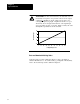
1
%
Signal Output
2
Pressure
3
Rotational Speed
00.00 to 99.99 %
0000 to 9999 PSI
000.0 to 999.9 RPM
000.0 to 999.9 Bar
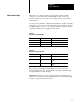
ATTENTION: You can connect up to four different valves to
your QDC module. Although all four may not directly jog the
ram (screw), consider their indirect effect when setting jog
set-output values. Indirectly, they could cause unexpected
machine motion with possible damage to equipment or injury to
personnel.