
Instruction Manual


Enter
Y
our Alarm and T
imedelay Values Here
Configure the QDC Module's I/O
Chapter 3
3-16
Set Up Maximum RPM and Pressure Alarms, and Time Delays
The QDC module continuously monitors screw RPM, ram (screw)
pressure, and cavity pressure inputs. When it detects that the process input
equals or exceeds a preset alarm setpoint, the QDC module sets an alarm
bit. A setpoint of zero disables the associated alarm.
To guard against nuisance alarms caused by noise spikes or pressure
transients , you can set a time delay so the QDC module must monitor
continuous excessive pressure or RPM for an amount of time before setting
the high alarm. A setpoint of zero disables this delay.
Configure the QDC module for pressure and RPM alarms as follows:
1. Determine these values for ram (screw) and/ or cavity pressure
alarms:
pressure-alarm setpoint
time-delay setpoint
2. Determine these values for screw RPM alarms:
RPM-alarm setpoint
time-delay setpoint
3. Record non-zero setpoints on Worksheet 3-G for the pressure alarms,
RPM alarm, and time delays you want to use.
4. Download them to the QDC module using the procedures presented
earlier in this chapter:
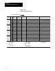
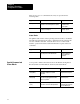
Worksheet 3G
Alarm
and T
imedelay Setpoints
Control Word ProSet 600 Addr. Value Description Units
MCC21 N40:17 Screw Pressurealarm Setpoint Ram (screw) Pressure
2
MCC22 N40:18 Screwpressure Timedelay Setpoint Time
Measured in Seconds
1
MCC55 N40:51 HighRPM Alarm Setpoint Rotational Speed
3
MCC56 N40:52 Screw RPM Timedelay Setpoint Time
Measured in Seconds
1
MCC61 N40:57 Cavity Pressurealarm Setpoint Cavity Pressure
4
MCC62 N40:58 Cavitypressure Timedelay Setpoint Time
Measured in Seconds
1
1
Time
Measured in Seconds
2
Pressure
3
Rotational Speed
4
Pressure
00.00
to 00.99
0000 to 9999 PSI
000.0 to 999.9 RPM
00000 to 20,000 PSI
000.0 to 999.9 Bar 0000.0 to 2000.0 Bar