
Instruction Manual
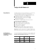
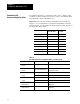

Select Input 1 (Screw Position) Range
Select Input 2 (Screw Pressure) Range
Select Input 3 (Screw RPM) Range
Select Input 4 (Cavity Pressure) Range
Input Range
0 - 10 vdc 0 0
1 - 5 vdc 0 1
4 - 20 mA 1 0
Not connected 1 1
Code:
Your value
Required initial value
loaded by ProSet 600
0
or 1
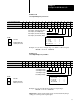
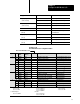
Select Output 1 Range
Select Output 2 Range
Select Output 3 Range
Select Output 4 Range
Output Range
-10 to +10 vdc 0 0
0 to +10 vdc 0 1
4 to 20 mA 1 0
Not connected 1 1
Code:
Your value
Required initial value
loaded by ProSet 600
0
or 1
Configure the QDC Module's I/O
Chapter 3
3-3
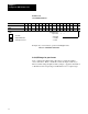
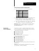
Worksheet 3B
Select Input Ranges for your Sensors
Control W
ord MCC03Bxx
15 14 13 12
11 10
09 08 07 06 05 04 03 02 01 00
ProSet 600 Addr. B34/bit
559 558 557 556 555 554 553 552 551 550 549 548 547 546 545 544
Value 1 1 1 1 1 1 1 1
Example: If you select an input range of 4-20mA for all four inputs,
MCC03 = 11111111 10101010.
Worksheet 3C
Select
Output Ranges for your V
alves
Control W
ord MCC04Bxx
15 14 13 12
11 10
09 08 07 06 05 04 03 02 01 00
ProSet 600 B34/bit
575 574 573 572 571 570 569 568 567 566 565 564 563 562 561 560
Value 1 1 1 1 1 1 1 1
Example: If you select 0-10 vdc for all four output ranges,
MCC04 = 11111111 01010101.
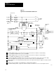
Important: Software input/output selections must match the jumper
settings for each respective input/output.