
Instruction Manual
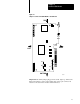

Install the QDC Module
Chapter 2
2-8
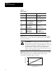
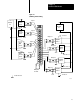
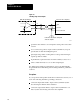
Table 2.B
I/O
T
erminal Designations
Transducer I/O Designation Terminal
Screw position Input 1 (+)
(-)
18
17
Screw pressure Input 2 (+)
(-)
16
15
Input common 14
Screw RPM Input 3 (+)
(-)
13
12
Cavity pressure Input 4 (+)
(-)
11
10
Valve 1 Output 1 (+)
Output common
09
08
Valve 2 Output 2 (+)
Output common
07
06
Valve 3 Output 3 (+)
Output common
05
04
Valve 4 Output 4 (+)
Output common
03
02
Not used 01
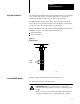
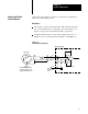
ATTENTION: The QDC module has ESD protection to 20KV,
but you can damage the module by accidental application of the
wrong voltage to the I/O terminals. Do not exceed:
This voltage On these terminals When in
+12vdc input (18 thru 10) any mode
+12vdc output (09 thru 02) voltage mode
+24vdc output (09 thru 02) current mode