
Instruction Manual
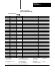

Enter
Y
our SWTL Configuration Values Here
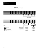
Enter Y
our Alarm and T
imedelay Values Here
Blank Worksheets
Appendix A
A-5
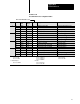
W
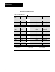
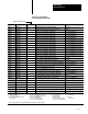
orksheet 3F
SWTL Configuration V
alues
Control Word ProSet 600
Addr
. Value Description Units
MCC13 N40:9 Screw Minimum SWTL Screw Axis Measured from zero
1
MCC14 N40:10 Screw Maximum SWTL Screw Axis Measured from zero
1
MCC15 N40:11 10 Screw SWTL Deadband As noted
1
1
Incremental Distance
00.00 to 99.99in
000.0 to 999.9mm
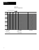
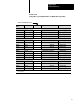
Worksheet
3G
Alarm and T
imedelay Setpoints
Control Word ProSet 600 Addr. Value Description Units
MCC21 N40:17 Screw Pressurealarm Setpoint Ram (screw) Pressure
2
MCC22 N40:18 Screwpressure Timedelay Setpoint Time
Measured in Seconds
1
MCC55 N40:51 HighRPM Alarm Setpoint Rotational Speed
3
MCC56 N40:52 Screw RPM Timedelay Setpoint Time
Measured in Seconds
1
MCC61 N40:57 Cavity Pressurealarm Setpoint Cavity Pressure
4
MCC62 N40:58 Cavitypressure Timedelay Setpoint Time
Measured in Seconds
1
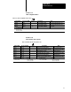
1
Time
Measured in Seconds
2
Pressure
3
Rotational Speed
4
Pressure
00.00
to 00.99
0000 to 9999 PSI
000.0 to 999.9 RPM
00000 to 20,000 PSI
000.0 to 999.9 Bar 0000.0 to 2000.0 Bar