
Instruction Manual

Span Your Valves
Chapter 9
9-2
We recommend that you first span your injection pressure valve for
optimum pressure performance. You do this in four parts:
Confirm critical values
Span your injection pressure valves
Test valve linearity with a pressure vs. time injection profile
Set profile pressure alarms
Important: You may omit the subsection Span Your Injection Pressure
Valve below if you have information from molding machine OEMs or
hydraulic valve manufacturers on spanning the working range of valves. If
available for your machine’s injection pressure valve(s), enter valve
spanning values into pressure control limits INC41-44 and proceed to Test
Valve Linearity. First confirm your critical values.
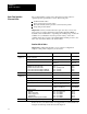
Confirm Critical Values
Important: Confirm that all values you recorded for configuration
(chapter 7) and profiles (chapter 8) are as follows:
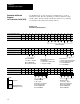
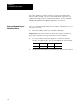
On Worksheet Confirm Your Configuration With These Words or Bits ProSet Addr.
7A
(chapter 7)
QDC module output to which you connected your
pressure control valve
INC02B06, B05, B04 B38/20, 21, 22
Setoutput values for unselected valves INC0912 = your values N44:5, 6, 7, 8
All ramping is disabled with zero ramp rates INC1720 = 0
INC2528 = 0
N44:1316
N44:2124
Pressure limits:
Minimum Pressure Control Limit
Maximum Pressure Control Limit
Selected Pressure Valve, Output for Minimum
Selected Pressure Valve, Output for Maximum
INC41 = 0
INC42 = system pressure
INC43 = your value
INC44 = your value
N44:37
N44:38
N44:39
N44:40
7C Endofprofile setoutput values HDC3336 for zero output N44:209212
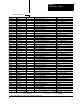
8A
(chapter 8)
Pressure vs Time algorithm IPC03B01 = B00 = 1 B38/9697
Openloop control IPC04B03 = B02 = B01 = B00 = 1 B38/112115
Expert Response Compensation (ERC) is disabled IPC04B11 = B10 = B09 = B08 = 1 B38/120123
Pressure setpoints IPC10,14,18,22,26,30,34,38,42,46,50
all equal to onehalf system pressure
start @ N44:66
end @ N44:106
Time setpoints IPC12,16,20,24,28,32,36,40,44,48
all equal to 1 second (100)
start @ N44:68
end @ N44:104
Transition setpoints
Time limit
Ram (screw) position
Ram (screw) pressure
Cavity pressure
Minimum position for pressure transition
IPC60 = 10 seconds (1000)
IPC61 = zero to inhibit
IPC62 = zero to inhibit
IPC63 = zero to inhibit
IPC64 = zero to inhibit
N44:116
N44:117
N44:118
N44:119
N44:120
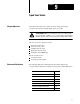
8B Logical bridge to stop and set outputs HPC03B08 = 1 B38/296
If these are not your current values, we suggest that you correct them now
using the download procedure discussed in chapter 4.
Span
Y
our Injection
Pressure V
alve