Plastic Molding Module (Cat. No.
Important User Information Because of the variety of uses for the products described in this publication, those responsible for the application and use of this control equipment must satisfy themselves that all necessary steps have been taken to assure that each application and use meets all performance and safety requirements, including any applicable laws, regulations, codes and standards.
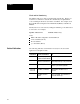
Summary of Changes Summary of Changes Summary of Changes We revised this publication to include changes due to upgrading the 1771-QDC/B module to a 1771-QDC/C. For These Changes Refer to Page(s) Loss of sensor detection input range changed back to 0.00 to 10V dc 3 5, 3 10 A 3, A 4 Added the section, Record I/O Ranges. 2 1 Added the title Ground and Shield Your I/O Devices to better describe the task.
Table of Contents Summary of Changes . . . . . . . . . . . . . . . . . . . . . . . . . . . . 1 1 Use This Preface . . . . . . . . . . . . . . . . . . . . . . . . . . . . . . . . P 1 Manual Objectives . . . . . . . . . . . . . . . . . . . . . . . . . . . . . . . . . . . Audience . . . . . . . . . . . . . . . . . . . . . . . . . . . . . . . . . . . . . . . . . . Use of Terms . . . . . . . . . . . . . . . . . . . . . . . . . . . . . . . . . . . . . . . Related Publications . . . . . . . . . . . . . . . .
ii Table of Contents Jog Your Machine . . . . . . . . . . . . . . . . . . . . . . . . . . . . . . . 5 1 Chapter Objectives . . . . . . . . . . . . . . . . . . . . . . . . . . . . . . . . . . . About Jogging . . . . . . . . . . . . . . . . . . . . . . . . . . . . . . . . . . . . . . Use These Worksheets . . . . . . . . . . . . . . . . . . . . . . . . . . . . . . . Determine Initial Jog Values . . . . . . . . . . . . . . . . . . . . . . . . . . . . Write Ladder Logic . . . . . . . . . . . . . . . . . . .
Table of Contents iii Determine Word Values for Worksheet 8 B . . . . . . . . . . . . . . . . . . Enter and Download your Worksheet Values . . . . . . . . . . . . . . . . Determine and Record Setpoints for Plastication Profile (PPC) . . . . Determine Bit Selections for Worksheet 8 C . . . . . . . . . . . . . . . . . Determine Word Values for Worksheet 8 C . . . . . . . . . . . . . . . . . . Enter and Download your Worksheet Values . . . . . . . . . . . . . . . .
Preface Use This Preface Manual Objectives Use this preface to familiarize yourself with this manual so you can use it effectively. This manual shows you how to apply the QDC module to your molding machine in the minimum length of time. Since this manual is task oriented, we recommend that you perform these tasks in the following order: Perform this task: Browse through the entire manual to become familiar with its contents. As discussed in this chapter: All chapters Overview the inject process.
Preface Audience In order to apply the QDC module to a molding machine, we assume that you are an: injection molding professional experienced programmer with Allen-Bradley PLC-5 processors hydraulics designer or technician Use of Terms We use these abbreviations: Abbreviated Name: Item QDC module 1771 QDC Plastic Molding Module PLC processor PLC 5 Processor T45 or T47 T50 or T53 terminal 1784 T45 or T47 1784 T50 or T53 Industrial Terminal Pro Set 600 Software 6500 PS600 Pro Set 600 Injectio
Preface Command Blocks Command blocks provide the parameters that control machine operation. They are transferred from the PLC processor to the QDC module by means of block transfer write (BTW) instructions in software ladder logic.
Preface Word and bit Numbering The QDC module stores data in command and status blocks. Each word location in a command or status block is identified by an alphanumeric code containing the block acronym and word number. For example, word 09 of the Module Configuration Command Block (MCC) is identified as MCC09. Identify bits in a word location by adding bit numbering to the abbreviated word location.
Preface Take time now to familiarize yourself with the Reference Manual, publication 1771-6.5.88.
Chapter 1 Overview of Inject Mode Chapter Objectives This chapter presents an overview of the 1771-QDC Plastic Molding Module in the Inject mode. We present a summary of Inject features followed by sample applications. Important: This manual assumes you have already read your Plastic Molding Module Application Guide, publication 1771-4.10, and have chosen Inject as your QDC module’s mode of operation.
Chapter 1 Overview of Inject Mode Figure 1.1 Inject Operation of a Typical Machine Cycle Transition to Pack or Hold Injection Pack Hold Clamp & Eject Operation Plastication (Reload) PostDecompression PreDecompression Injection Phase You can vary the velocity of the ram (screw), or the pressure driving it, so the leading edge of the melt moves through the mold cavity at the desired speed. The pattern of velocity or pressure variation during injection is called the injection profile.
Chapter 1 Overview of Inject Mode With this Profile You Control Injection With up to 11 Segments Distributed over the Velocity vs. Position Speed Length of the shot Pressure-limited [1] Velocity vs. Position Speed, with a maximum pressure Length of the shot Pressure vs. Position Pressure Length of the shot Pressure vs. Time Pressure Time for a shot [1] Pressure-limited velocity vs. position profile differs from the velocity vs.
Chapter 1 Overview of Inject Mode Flash Prevention Example - With a velocity profile (figure 1.4 part 1), the pressure may reach a peak and flash the mold at ram (screw) position segments (part 2) that correspond to events such as: the initial surge (2.a) when the melt front enters a constriction in the mold cavity (2.b) You can remedy this (part 3) by decreasing the ram (screw) velocity at segments (3.a) and (3.b) that correspond to flash points. Conversely, you can boost velocity at segment (3.
Chapter 1 Overview of Inject Mode Injection to pack Transition The QDC module ends the injection phase and automatically starts the pack or hold phase when it detects the first of up to four events occurred: Ram (screw) position exceeds a preset limit Ram (screw) pressure exceeds a preset limit Cavity pressure exceeds a preset limit Injection phase elapsed time exceeds a preset limit You select which of these events you want monitored for transition by entering the appropriate setpoint, or zero for ignorin
Chapter 1 Overview of Inject Mode Example Benefits of Profiling the Pack Phase Molten plastic may cool unevenly in the mold causing variations in density with the end result of warpage and distortion as shown in Figure 1.6. Figure 1.
Chapter 1 Overview of Inject Mode Hold Phase The QDC module controls the hold phase with a pressure vs. time profile. You create the profile based on controlling hydraulic pressure against the ram (screw), or by controlling pressure within the mold cavity resulting from hydraulic pressure against the ram (screw). You can control either pressure with up to five time segments. You determine the pressure setpoints and time durations for the hold profile based on your molding requirements.
Chapter 1 Overview of Inject Mode Backpressure or Screw RPM Figure 1.8 Plastication Phase Example 1 2 hotter Mold End 3 4 6 5 7 Position or Time Temperature Gradient Barrel Containing the Melt 8 9 10 11 cooler Back Point Affects of Profiling a Plastication Phase Backpressure and/or screw RPM have these affects on plastication: The higher the backpressure (or screw RPM) during plastication, the higher the resultant temperature of the melt.
Chapter 2 Install the QDC Module Chapter Objectives This chapter guides you through the following installation procedures: record I/O ranges set module jumpers key your I/O chassis install your QDC module wire I/O devices to your QDC module ground your system plan for E-Stops and Machine Interlocks Record I/O Ranges To match your QDC module to your I/O devices, record the I/O ranges of your I/O devices on Worksheet 2-A.
Chapter 2 Install the QDC Module Set Module Jumper Plugs Before installing the QDC module, you must select with jumper plugs the I/O ranges that you recorded on Worksheet 2-A. Access and Position the Jumpers Access the jumpers and set them as follows: ATTENTION: To avoid damage to internal circuits, observe handling precautions and rid yourself of any electrostatic charge. Use an anti-static work station when setting jumper plugs. 2-2 1. Remove the label-side cover plate by removing the four screws.
Chapter 2 Install the QDC Module Figure 2.1 Jumper Locations on the QDC Module's Circuit Board TOP E1 E5 E6 LEFT RIGHT E7 E8 E9 E10 E11 E14 E12 E13 E15 E17 E16 BOTTOM 10908 I Important: We define jumper plug positions as left, right, top, and bottom. This represents the position of the jumper plug on the 3-pin connector as relative to the sides of the circuit board shown above.
Chapter 2 Install the QDC Module Table 2.
Chapter 2 Install the QDC Module Key Your I/O Chassis Use the plastic keying bands, shipped with each I/O chassis, for keying I/O slots to accept only one type of module. This is done to prevent the inadvertent installation of the wrong module into the wrong slot. The QDC module is slotted in two places on the rear edge of the circuit board. The position of the keying bands on the backplane connector must correspond to these slots to allow insertion of the module.
Chapter 2 Install the QDC Module Failure to remove power from the backplane or wiring arm could cause module damage, degradation of performance, or injury. 2. Place the module in the plastic tracks on the top and bottom of the slot that guides the module into position. Important: Be aware that Pro-Set 600 expects your QDC module to be placed in slot 0 of I/O rack 0 when operating in inject mode.
Chapter 2 Install the QDC Module Figure 2.
Chapter 2 Install the QDC Module Table 2.
Chapter 2 Install the QDC Module Ground and Shield Your I/O Devices Analog inputs and outputs are sensitive to electrical noise interference. Take care to shield them properly. Guidelines: Use 22-gage (or larger) twisted-pair cable, 100% shielded with drain wire, such as Belden 8761 (or equivalent). For cable distances over 50 ft, use 18-gage cable such as Belden 8760 (or equivalent) Ground the cable shield at one end only; generally at the sensor or amplifier end, not at the I/O chassis (see Figure 2.
Chapter 2 Install the QDC Module Figure 2.
Chapter 2 Install the QDC Module Plan for E Stops and Machine Interlocks You must consider the installation of Emergency Stop (E-STOP) switches and machine interlocks when you: design your system assemble mechanical/hydraulic components wire system components develop system ladder logic ATTENTION: The Electrical Standard for Industrial Machinery (NFPA 79-1987) requires an emergency stop that when actuated, shall de-energize all electrical power circuits which provide electrical energy to sustain machine
Chapter 2 Install the QDC Module Figure 2.
Chapter 3 Configure the QDC Module's I/O Chapter Objectives Your QDC module needs to know the characteristics of your ram (screw) sensors. In this chapter, we describe how you determine these characteristics and download them to the QDC module.
Chapter 3 Configure the QDC Module's I/O Worksheet 3 A Select Module Parameters Control Word MCC02 Bxx 15 14 13 12 11 10 09 08 07 06 05 04 03 02 01 00 Pro Set 600 Addr.
Chapter 3 Configure the QDC Module's I/O Worksheet 3 B Select Input Ranges for your Sensors Control Word MCC03 Bxx 15 14 13 12 11 10 09 08 07 06 05 04 03 02 01 00 Pro Set 600 Addr.
Chapter 3 Configure the QDC Module's I/O Determine Initial Sensor configuration Values To determine initial sensor configuration values, refer to Table 3.A and specifications that accompanied your sensors, valves, and cylinders. Write down applicable values on Worksheet 3-D. Important: You must enter floating-point numbers and percentages as integers, so we recommend that you write them in Worksheet 3-D in the following format: Use an assumed decimal point position that depends on the range value.
Chapter 3 Configure the QDC Module's I/O Category: If your: Then Use a Value Equal to: Analog Signal @ Min Pressure sensors are forward acting low end of your selected range sensors are reverse acting high end of your selected range sensors are forward acting high end of your selected range sensors are reverse acting low end of your selected range Minimum Screw RPM (Line 9) N/A zero Maximum Screw RPM (Line 10) N/A max range value specified by the manufacturer Analog Signal @ Min RPM sens
Chapter 3 Configure the QDC Module's I/O Download MCC Values to the QDC Module Use this download procedure now and later in this chapter.
Chapter 3 Configure the QDC Module's I/O Important: Pro-Set 600 software downloads all command blocks when your PLC-5 processor enters run mode after a valid MCC block is accepted. All programming errors reported in SYS62 (N40:214) are referenced to the MCC block until SYS01-B08 = 1. Correct Any Data entry (Programming) Errors in MCC Upon receipt of the MCC block, the QDC module tests data for data-entry errors, such as a value out of range.
Chapter 3 Configure the QDC Module's I/O Use Set Output Operation to Move the Ram (Screw) To finish configuring the QDC module, you actuate the ram (screw) with the QDC module’s set-output operation that applies percentage values to your QDC module’s outputs to move the ram (screw) in a controllable fashion. To do this, you apply %-output signals to all module outputs so you can move the actuator over its intended range.
Chapter 3 Configure the QDC Module's I/O Actuate the Ram (screw) with Set output Operation 1. Enter values that result in no motion in these DYC words Output: In Data Word: At Pro Set 600 Address: 1 DYC09 N40:121 2 DYC10 N40:122 3 DYC11 N40:123 4 DYC12 N40:124 2. Enable set-output operation by entering a 1 in DYC01-B08 (Pro-Set 600 address B34/392). The QDC module sets outputs 1 - 4 to percentage values that you entered in DYC09 - DYC12 respectively. 3.
Chapter 3 Configure the QDC Module's I/O Worksheet 3 E Final Sensor configuration Values Enter Your Final Values Here Input 1 2 3 4 3-10 Line Control Word Pro Set 600 Address Value Units Minimum Screw Position Screw Axis Measured from zero 1 1 MCC09 N40:5 2 MCC10 N40:6 Maximum Screw Position Screw Axis Measured from zero 1 3 MCC11 N40:7 Analog Signal @ Min Screw Position Input Signal Range 2 4 MCC12 N40:8 Analog Signal @ Max Screw Position Input Signal Range 2 5 MCC17 N40:13
Chapter 3 Configure the QDC Module's I/O Determine Values for the Ram (Screw) Position Sensor ATTENTION: Incorrect values entered in DYC09 through DYC12 may result in rapid ram (screw) motion and potential damage to your barrel or seals of your injection cylinder.
Chapter 3 Configure the QDC Module's I/O Determine Values for the Ram (Screw) Pressure Sensor To complete the configuration for your ram (screw) pressure sensor, enter on Worksheet 4-E minimum and maximum pressures and corresponding signal levels from manufacturer’s specifications in MCC17-20. Most applications require no further spanning. If your application requires greater accuracy, follow the procedure below: 1. Release system pressure to obtain minimum ram (screw) pressure. 2.
Chapter 3 Configure the QDC Module's I/O You may now download your adjusted values to the QDC module using the MCC download procedure presented earlier in this chapter. Determine Values for the Cavity Pressure Sensor (if used) To complete the configuration for your cavity pressure sensor, enter in Worksheet 4-E minimum and maximum pressures and corresponding signal levels from manufacturer’s specifications in MCC57-60. Most applications require no further spanning.
Chapter 3 Configure the QDC Module's I/O 8. With your programming terminal, read the signal level returned in SYS35 (N40:187) from your RPM sensor. You may wish to span your RPM sensor at this time. 9. Record this signal level on line 12 for MCC54. 10. Release all flow and pressure from your screw motor and allow the screw to return to rest. You may now download your adjusted values to the QDC module using the MCC download procedure presented earlier in this chapter.
Chapter 3 Configure the QDC Module's I/O ignores all profile commands (except set-outputs and jogs) until you jog the cylinder back through the deadband into the safe zone at either end The deadband guards against sensor noise flickering the SWTL alarms and requires the operator to jog the cylinder a set distance away from the software overtravel. We recommend a value of 00.10 inch as a starting deadband. Your sensor may require a greater deadband.
Chapter 3 Configure the QDC Module's I/O Set Up Maximum RPM and Pressure Alarms, and Time Delays The QDC module continuously monitors screw RPM, ram (screw) pressure, and cavity pressure inputs. When it detects that the process input equals or exceeds a preset alarm setpoint, the QDC module sets an alarm bit. A setpoint of zero disables the associated alarm.
Chapter 3 Configure the QDC Module's I/O Configure a Digital Filter for the Position Input from the Ram (Screw) You may enable an optional digital filter on position inputs to reduce electrical noise from a potentiometer-type position sensor or picked up by your input circuits. To determine if you need a digital filter, move the ram (screw) very slowly. With your programming terminal, look for erratic position numbers reported for ram (screw) position by examining SYS25 (N40:177).
Chapter 4 Overview of Remaining Configuration Procedures Chapter Objectives This chapter introduces you to the remaining procedure necessary to successfully configure your QDC module. You must follow the procedures in the order given. Please use this chapter as a guide. Configuration Concepts The QDC module communicates with your PLC-5 processor through data blocks. These blocks are made up of several 16 bit words stored in the PLC-5 data table.
Chapter 4 Overview of Remaining Configuration Procedures There are two types of command blocks. They are presented in the following table. Type Which Contain Examples Configuration Blocks Information necessary to configure your module to run a certain portion of a profile Valve spanning information for the injection profile Profile Blocks Actual process setpoints necessary to produce a desired part.
Chapter 4 Overview of Remaining Configuration Procedures Overview of Remaining Configuration Procedures Configuration procedures detailed in the next several chapters are outlined below. The procedures are sequential in nature: configuration information determined in initial chapters is needed in later chapters. Step Procedure Information that you enter: Refer to: 1 Jog Your Machine Machine jog pressure and flow setpoints are entered into the Jog Configuration block (JGC).
Chapter 4 Overview of Remaining Configuration Procedures Enter Data Table Values and Download Command Blocks We refer to these procedures throughout this manual whenever you must: enter data table values download command blocks Enter Values into Your PLC 5 Data Table With your programming terminal, enter worksheet values into your PLC-5 data table as follows: 1. Switch the PLC-5 processor to PROGRAM mode. 2. Display your PLC-5 data table 3.
Chapter 4 Overview of Remaining Configuration Procedures Learn the following procedure because you will use it often. 1. For the block you want to download (subject block), get its ID number from Table 4.A and enter it into DYC61. Table 4.
Chapter 4 Overview of Remaining Configuration Procedures 3. Start the download procedure by setting the corresponding download bit (Table 4.A) in your PLC-5 data table. 4. Watch the bit you set in step 3 and wait for Pro-Set 600 software to reset it to zero. This indicates the PLC-5 processor has transferred the block to the QDC module. 5. Observe the value of SYS62 (N40:214) in your PLC-5 data table: If SYS62 = 0, the QDC module detected no errors. Go to step 6.
Chapter 5 Jog Your Machine Chapter Objectives This chapter describes how to: configure all jog block values necessary to jog your ram (screw) test jog values and make changes, if necessary configure values which may indirectly affect clamp and eject jogs About Jogging Jogging your machine is similar to operating it in set-output operation: You apply percentage values to your QDC module’s outputs to obtain the desired motion.
Chapter 5 Jog Your Machine Determine Initial Jog Values Worksheet 5-A lists all words in which you must enter values to successfully configure your QDC module for jogging the ram (screw). Use it to record: initial values Enter initial values just sufficient to jog in the desired direction. Keep this information in mind: The numbers you enter are %-signal output. For a range of –10 to +10vdc, zero output occurs @ 50% (See Warning on next page.
Chapter 5 Jog Your Machine Worksheet 5.
Chapter 5 Jog Your Machine ATTENTION: A value of 0 entered in your data table does not necessarily correspond to zero pressure or flow. For an output configured + 10VDC, an output of 50% corresponds to zero volts signal output (see graph). Amplifier electronics or spool offsets may also be designed such that zero volts signal input does not result in no flow or pressure. Please consult your valve and amplifier specifications for more details.
Chapter 5 Jog Your Machine Write Ladder Logic Take time now to develop ladder logic (independent of Pro-Set 600 software) to jog the ram (screw) with the QDC module. You need to monitor switches on your operator control panel, and set corresponding command bits. Use word 1 in the dynamic command block (DYC01) to enable and disable individual jogs. Use word 1 in the system status block (SYS01) to monitor the QDC module’s reaction to jog commands. Tables 5.A and 5.
Chapter 5 Jog Your Machine Figure 5.
Chapter 5 Jog Your Machine Jog Your Ram (Screw) Jog your ram (screw) in forward and reverse directions. Experiment with values you entered in the jog configuration block (JGC) until you obtain the desired jog operation. You must download the JGC to the QDC module each time you change a value in the command block to implement the new value. Refer to the download procedure outlined in chapter 4.
Chapter 5 Jog Your Machine Worksheet 5. B Clamp & Eject Jog Configuration Values for QDC Module in Inject Mode Enter Your Initial Values Here Control Block Word Pro Set 600 Addr.
Chapter 5 Jog Your Machine Write Ladder Logic to Assist with Clamp & Eject Jogs If your hydraulics require it, take time now to develop ladder logic (independent of Pro-Set 600 software) so the QDC module (in inject mode) can assist jogging the clamp and ejector. Otherwise, omit the rest of this chapter. Use word 1 in the dynamic command block (DYC01) to enable and disable individual jogs. Use word 1 in the system status block (SYS01) to monitor the QDC module’s reaction to jog commands. Tables 5.C and 5.
Chapter 5 Jog Your Machine Figure 5.
Chapter 6 Select Command and Status Bits to Sequence Machine Operation Chapter Objectives In this chapter, we provide you with tables of command and status bits that you use to write ladder logic to: implement manual functions such as jog, set outputs, and stop step your QDC module through machine cycles We suggest how to assess your logic requirements and based on those requirements how to use bit tables to write your machine’s sequential ladder logic that depends on your machine’s hydraulic configurat
Chapter 6 Select Command and Status Bits To Sequence Machine Operation Use Command and Status Bit Tables Use the following tables to select command and status bits when writing ladder logic to control manual functions and machine sequencing. Table 6.
Chapter 6 Select Command and Status Bits To Sequence Machine Operation Table 6.
Chapter 6 Select Command and Status Bits To Sequence Machine Operation Table 6.
Chapter 6 Select Command and Status Bits To Sequence Machine Operation Table 6.
Chapter 7 Load Initial Configuration Values Chapter Objectives This chapter helps you determine, enter, and download configuration setpoints required to tune the QDC module. You will refer to this chapter frequently when tuning the QDC module in chapter 9.
Chapter 7 Load Initial Configuration Values Use These Worksheets The following table lists command blocks and corresponding worksheets for recording your initial values that you use to configure the QDC module.
Chapter 7 Load Initial Configuration Values This page is purposely blank so that the following 2-page worksheets will be on facing pages.
Chapter 7 Load Initial Configuration Values Worksheet 7 A Injection Configuration Command Block (INC) Control Word INC01 Bxx 15 14 13 12 11 10 09 08 07 06 05 04 03 02 01 00 Pro Set 600 Addr. B38/bit 15 14 13 12 11 10 09 08 07 06 05 04 03 02 01 00 Value 0 0 0 0 0 0 0 0 0 0 0 0 1 0 0 0 INC Block Identifier Control Word INC02 Bxx 15 14 13 12 11 10 09 08 07 06 05 04 03 02 01 00 Pro Set 600 Addr.
Chapter 7 Load Initial Configuration Values Worksheet 7 A (continued) Injection Configuration Command Block (INC) Enter Your Values Here Control Word Pro Set 600 Addr.
Chapter 7 Load Initial Configuration Values Worksheet 7 B Pack Configuration Command Block (PKC) Control Word PKC01 Bxx 15 14 13 12 11 10 09 08 07 06 05 04 03 02 01 00 Pro Set 600 Addr. B38/bit 143 142 141 140 139 138 137 136 135 134 133 132 131 130 129 128 0 0 0 0 0 0 0 0 0 0 0 0 1 0 1 0 Value PKC Block Identifier Control Word PKC02 Bxx 15 14 13 12 11 10 09 08 07 06 05 04 03 02 01 00 Pro Set 600 Addr.
Chapter 7 Load Initial Configuration Values Worksheet 7 B (continued) Pack Configuration Command Block (PKC) Enter Your Values Here Control Word Pro Set 600 Addr.
Chapter 7 Load Initial Configuration Values Worksheet 7 C Hold Configuration Command Block (HDC) Control Word HDC01 Bxx 15 14 13 12 11 10 09 08 07 06 05 04 03 02 01 00 Pro Set 600 Addr. B38/bit 207 206 205 204 203 202 201 200 199 198 197 196 195 194 193 192 0 0 0 0 0 0 0 0 0 0 0 0 1 0 1 1 Value HDC Block Identifier Control Word HDC02 Bxx 15 14 13 12 11 10 09 08 07 06 05 04 03 02 01 00 Pro Set 600 Addr.
Chapter 7 Load Initial Configuration Values Worksheet 7 C (continued) Hold Configuration Command Block (HDC) Enter Your Values Here Control Word Pro Set 600 Addr.
Chapter 7 Load Initial Configuration Values Worksheet 7 D Plastication Configuration Block (PLC) Control Word PLC01 Bxx 15 14 13 12 11 10 09 08 07 06 05 04 03 02 01 00 Pro Set 600 Addr. B38/bit 399 398 397 396 395 394 393 392 391 390 389 388 387 386 385 384 0 0 0 0 0 0 0 0 0 0 0 0 1 1 1 0 Value PLC Block Identifier Control Word PLC02 Bxx 15 14 13 12 11 10 09 08 07 06 05 04 03 02 01 00 Pro Set 600 Addr.
Chapter 7 Load Initial Configuration Values Worksheet 7 D (continued) Plastication Configuration Block (PLC) Enter Your Values Here Control Word Pro Set 600 Addr.
Chapter 7 Load Initial Configuration Values Procedure to Determine and Enter Initial Values Follow this procedure to complete each worksheet: 1. Read the text for the subject parameter. 2. Determine your initial value. Important: If you need additional information when determining your initial values, refer to the same configuration blocks in Section 3 of the Plastic Molding Module Reference Manual, publication 1771-6.5.88. 3.
Chapter 7 Load Initial Configuration Values B02 B01 B00 Selects: 0 0 0 Output #1 Used for RPM Control 0 0 1 Output #2 Used for RPM Control 0 1 0 Output #3 Used for RPM Control 0 1 1 Output #4 Used for RPM Control Record the appropriate bit selections for your valve configurations in the control word of worksheet 7-D. Selected Control Valve for Ram (Screw) Pressure (INC02, PKC02, HDC02, and PLC02) The QDC module can control ram (screw) movement using pressure vs.
Chapter 7 Load Initial Configuration Values Select the Type of PID Algorithm Type of PID Algorithm (INC02, PKC02, HDC02, and PLC02) When executing pressure or screw RPM versus position or time profiles, the QDC module can use one of two types of PID algorithms: dependent gains (ISA) or independent gains (Allen-Bradley).
Chapter 7 Load Initial Configuration Values Important: These recorded PID gain constants and closed-loop tuning procedures in chapter 10 assume the selection of independent (A-B) gains. If, after attempting to tune your pressure loops in chapter 10, you believe you must use dependent (ISA) gain constants, refer to section 3 of the Reference Manual (1771-6.5.88) for information on this option.
Chapter 7 Load Initial Configuration Values Table 7.
Chapter 7 Load Initial Configuration Values Output Voltage ATTENTION: A value of 0 entered in your set-output words does not necessarily correspond to zero pressure or flow. If you configured for bi-directional valve operation (–10 to + 10VDC), an output value of 50% gives a zero volts signal output (see graph) while an output value of 0% or 100% gives a maximum signal output . Amplifier electronics or spool offsets may also allow pressure or flow at zero volts signal input.
Chapter 7 Load Initial Configuration Values Acceleration Ramp Rates (INC17 20, PKC17 20, HDC17 20, and PLC17 20) The QDC module uses acceleration ramp rates when moving its outputs to a higher setpoint during execution of a profile. They affect both selected and unselected valves. A ramp rate of zero disables ramping, and the QDC module steps directly from setpoint to setpoint. We recorded zero on corresponding worksheets.
Chapter 7 Load Initial Configuration Values Set Pressure Control Limits Setting pressure control limits lets you span your selected valve outputs for effective control with either direct- or reverse-acting valves. Your machine manufacturer typically provides you with values to configure these limits. Minimum Ram (Screw) Pressure Control Limit (INC41, PKC41, HDC41, and PLC41) The value in this word corresponds to the minimum controllable ram (screw) pressure during the respective profile.
Chapter 7 Load Initial Configuration Values Selected Ram (Screw) Pressure Valve, Output for Maximum (INC44, PKC44, HDC44, and PLC44) The QDC module uses this word with Maximum Ram (Screw) Pressure Control Limit (word 42) above. Enter the %-signal output that the QDC module uses to drive the selected ram (screw) pressure valve for maximum profile pressure. The QDC expects a pressure equal to word 42 when setting the selected ram (screw) pressure valve to this percentage output.
Chapter 7 Load Initial Configuration Values Selected Cavity Pressure Valve, Output for Minimum (PKC47and HDC47) The QDC module uses this word with Minimum Cavity Pressure Control Limit (word 45) above. Enter the %-signal output that the QDC module uses to drive the selected cavity pressure valve for minimum profile pressure. The QDC module expects a pressure equal to word 45 when setting the selected cavity pressure valve to this %-output.
Chapter 7 Load Initial Configuration Values Set Velocity Control Limits Minimum Velocity Control Limit (INC45) The value in this word corresponds to the minimum controllable ram (screw) velocity during the injection profile. The QDC module uses this word with Selected Velocity Valve, Output for Minimum (INC47) below. The QDC module expects this velocity when setting its selected velocity valve to the percentage output you enter in INC47. We recorded zero on Worksheet 7-A.
Chapter 7 Load Initial Configuration Values Selected Velocity Valve, Output for Maximum (INC48) The QDC module uses this word with Maximum Velocity Control Limit (INC46) above. Enter the %-signal output that the QDC module uses to drive the selected velocity valve for maximum profile velocity. The QDC module expects a velocity equal to INC46 when setting the selected velocity valve to this %-output.
Chapter 7 Load Initial Configuration Values Maximum RPM Control Limit (PLC46) The value in this word corresponds to the maximum controllable RPM during the plastication profile. The QDC module uses this word with the Selected RPM Valve, Output for Maximum (word 48) below. The QDC module expects this RPM when setting the selected RPM valve to the percentage output you enter in word 48. Record the maximum screw RPM per your OEM specifications on Worksheet 7-D.
Chapter 7 Load Initial Configuration Values Determine Output for Maximum values as follows: 9999 (100%) for uni-directional direct acting valves 0 (0%) or 9999 (100%) for bi-directional valves depending on direction 0 (0%) for uni-directional reverse acting valves If your selected pressure valve is: Then the value in word 48 should be: And during the profile, the QDC module does NOT drive the valve with a % output: Direct Acting greater than the value in word 47 greater than the value in word 48 Reve
Chapter 7 Load Initial Configuration Values Watchdog Timer Preset (PLC08) Use the watchdog timer to signal an alarm if the plastication profile takes longer than expected. To inhibit the timer, enter a preset of zero.
Chapter 8 Load Initial Profile Values Chapter Objectives This chapter describes how to load setpoints for inject-mode profiles. You determine initial values and enter setpoints into PLC-5 data table for the following profiles: Injection Profile (IPC) Pack/Hold Profile (HPC) Plastication Profile (PPC) Then, you download them to the QDC module. Important: This chapter continues the procedure for loading information into the QDC module. Complete chapter 7 before starting this chapter.
Chapter 8 Load Initial Profile Values Determine and Record Setpoints for the Injection Profile (IPC) Use Worksheet 8-A to enter setpoints for pressure vs. time and velocity vs. position injection profiles. The valve spanning procedures in chapter 9 require specific values. We have already entered many values for you, and help you determine other values in the text that follows.
Chapter 8 Load Initial Profile Values IPC15 IPC16 IPC17 IPC18 IPC19 IPC20 IPC21 IPC22 IPC23 IPC24 IPC25 IPC26 IPC27 IPC28 IPC29 IPC30 IPC31 IPC32 IPC33 IPC34 IPC35 IPC36 IPC37 IPC38 IPC39 IPC40 IPC41 IPC42 IPC43 IPC44 IPC45 IPC46 IPC47 IPC48 IPC49 IPC50 IPC51 IPC52 IPC57 IPC58 IPC59 IPC60 IPC61 IPC62 IPC63 IPC64 1 N44:71 N44:72 N44:73 N44:74 N44:75 N44:76 N44:77 N44:78 N44:79 N44:80 N44:81 N44:82 N44:83 N44:84 N44:85 N44:86 N44:87 N44:88 N44:89 N44:90 N44:91 N44:92 N44:93 N44:94 N44:95 N44:96 N44:97 N44:9
Chapter 8 Load Initial Profile Values Determine Bit Selections for Worksheet 8 A Injection Profile Block Identifier (IPC01) Bits 07-00 of this word identify it as the first word in a series used to define the injection profile. These bits must be set to 00001001. We recorded these bits on Worksheet 8-A. Velocity Units (IPC03) The following bit determines units of measure for injection velocity values. -BIT 14 selects units of measure.
Chapter 8 Load Initial Profile Values Expert Response Compensation (IPC04) -BITS 11, 10, 09, and 08 determine whether you apply Expert Response Compensation (ERC) to injection profiles. ERC is an exclusive algorithm that adjusts for changes in your machine, hydraulics, raw materials, and other process variables. It compensates for abrupt upsets and long term deviations.
Chapter 8 Load Initial Profile Values Pressure Setpoints (IPC10, 14, 18, 22, 26, 30, 34, 38, 42, 46, and 50) Use these words when configuring pressure vs. position or time profiles. Enter pressure in PSI or Bar. Each pressure setpoint controls the pressure of its corresponding segment. You may use from 1 to 11 segments in your profile. The procedures in chapter 9 require all eleven. Record the initial value of one-half system pressure for all 11 pressure setpoints on Worksheet 8-A.
Chapter 8 Load Initial Profile Values Time Setpoints (IPC12, 16, 20, 24, 28, 32, 36, 40, 44, and 48) Use these words when configuring pressure vs.time profiles. Enter time in seconds (1 second as 100). Each setpoint controls the time of its own segment. You must use one less time setpoint than pressure setpoints. We recorded 1 second (100) for these time setpoints on Worksheet 8-A. The valve spanning procedures in chapter 9 require these initial values.
Chapter 8 Load Initial Profile Values Transition Setpoints (IPC60, 61, 62, 63, and 64) Use these words when configuring the type of transition from injection to the pack (or hold) profile. The QDC module starts the transition when it detects the first of the following conditions that you enable with a non-zero setpoint. You may enable one or more of the following: -IPC60 determines the transition time limit.
Chapter 8 Load Initial Profile Values -IPC64 determines the position at which the QDC module begins to allow pressure transitions. A non-zero value measured from the mold end forces the QDC module NOT to transition on pressure until the ram (screw) reaches this position. A zero setpoint forces the QDC module to use any non-zero setpoint in IPC62 or IPC63 over the entire injection profile. We recorded zero on Worksheet 8-A to inhibit this function.
Chapter 8 Load Initial Profile Values Worksheet 8 B Pack/Hold Profile Command Block (HPC) Control Word HPC01 Bxx 15 14 13 12 11 10 09 08 07 06 05 04 03 02 01 00 Pro Set 600 Addr. B38/bit 271 270 269 268 267 266 265 264 263 262 261 260 259 258 257 256 0 0 0 0 0 0 0 0 0 0 0 0 1 1 0 0 Value HPC Block Identifier Control Word HPC03 Bxx 15 14 13 12 11 10 09 08 07 06 05 04 03 02 01 00 Pro Set 600 Addr.
Chapter 8 Load Initial Profile Values Worksheet 8 B (continued) Pack/Hold Profile Command Block (HPC) Enter Your Values Here Control Word Pro Set 600 Addr.
Chapter 8 Load Initial Profile Values Determine Bit Selections for Worksheet 8 B Pack/Hold Profile Block Identifier (HPC01) Bits 07-00 of this word identify it as the first word in a series used to define the pack/hold profile. These bits must be set to 00001100. We recorded these bits on Worksheet 8-B. Profile Offset Sign (HPC03) Profile offsets let you shift the amplitude of entire profiles up or down, if necessary. The offset sign determines the direction of shift.
Chapter 8 Load Initial Profile Values Profile Algorithm (HPC03) The following bits of HPC03 determine whether the pack and/or hold profiles use the ram (screw) or cavity pressure algorithm. -BIT 02 selects the algorithm for the hold profile. -BIT 00 selects the algorithm for the pack profile. 0 = Ram (screw) pressure vs. time 1 = Cavity pressure vs. time We recorded these bits = 0 for ram pressure vs. time on Worksheet 8-B. Important: All other bit selections in HPC03 should be zero.
Chapter 8 Load Initial Profile Values Determine Word Values for Worksheet 8 B Cavity Pressure Setpoints (for pack profile: HPC09, 12, 15, 18, and 21) (for hold profile: HPC26, 29, 32, 35, and 38) Use these words when configuring cavity pressure vs. time pack or hold profiles. You enter pressure in PSI or Bar. Each setpoint controls the pressure of its corresponding segment.
Chapter 8 Load Initial Profile Values Profile Offsets (for Pack profile: HPC24 and 25) (for Hold profile: HPC41 and 42) Profile offsets let you shift the amplitude of the entire pack or hold profile up or down, if necessary. You enter these setpoints in PSI or Bar. -HPC24 and 41 determine the offset for cavity pressure profiles. -HPC25 and 42 determine the offset for ram pressure profiles. We recorded zeros for no pressure offsets on Worksheet 8-B.
Chapter 8 Load Initial Profile Values Determine and Record Setpoints for Plastication Profile (PPC) Use Worksheet 8-C to enter setpoints for a backpressure vs. position plastication profile. The valve spanning procedures in chapter 9 require specific values. We have already entered many values for you, and help you determine other values in the text that follows.
Chapter 8 Load Initial Profile Values Enter Your Values Here Control Word PPC09 PPC10 PPC11 PPC12 PPC13 PPC14 PPC15 PPC16 PPC17 PPC18 PPC19 PPC20 PPC21 PPC22 PPC23 PPC24 PPC25 PPC26 PPC27 PPC28 PPC29 PPC30 PPC31 PPC32 PPC33 PPC34 PPC35 PPC36 PPC37 PPC38 PPC39 PPC40 PPC41 PPC42 PPC43 PPC44 PPC45 PPC46 PPC47 PPC48 PPC49 PPC50 PPC51 PPC52 PPC61 PPC62 1 Pro Set 600 Addr.
Chapter 8 Load Initial Profile Values Determine Bit Selections for Worksheet 8 C Plastication Profile Block Identifier (PPC01) Bits 07-00 of this word identify it as the first word in a series used to define the plastication profile. These bits must be set to 00001111. We recorded these bits on Worksheet 8-C. Profile Offset Sign (PPC03) Profile offset lets you shift the amplitude of entire profiles up or down, if necessary. The offset sign determines the direction of shift.
Chapter 8 Load Initial Profile Values Expert Response Compensation (PPC04) -BITS 11, 10, 09, and 08 determine whether you apply Expert Response Compensation (ERC) to plastication profiles. ERC is an exclusive algorithm that adjusts for changes in your machine, hydraulics, raw materials, and other process variables. It compensates for abrupt upsets and long term deviations. 0 = Expert Response Compensation ON 1 = Expert Response Compensation OFF We recorded these bits = 1 (ERC = Off) on worksheet 8-C.
Chapter 8 Load Initial Profile Values Backpressure Setpoints (PPC10, 14, 18, 22, 26, 30, 34, 38, 42, 46, and 50) Use these words when configuring backpressure vs. position or time profiles. You enter pressure in PSI or Bar. Each setpoint controls the pressure of its corresponding segment. You may use from 1 to 11 segments in your profile. The procedures in chapter 9 require all eleven.
Chapter 8 Load Initial Profile Values The valve spanning procedures in chapter 9 require these initial values. For additional information, refer to the Plastic Molding Module Reference Manual (publication 1771-6.5.88). Time Setpoints (PPC12, 16, 20, 24, 28, 32, 36, 40, 44, and 48) Use these words when configuring either one of the following profiles: backpressure vs time RPM vs time Each setpoint controls the time (in seconds) of its corresponding segment.
Chapter 8 Load Initial Profile Values The valve spanning procedures in chapter 9 require these initial values. Where required, we help you select correct final values required by your application in chapter 10. For additional information, refer to the Plastic Molding Module Reference Manual (publication 1771-6.5.88). Enter and Download your Worksheet Values After you determine initial values and record them on Worksheet 8-C, you are ready to proceed. 1.
Chapter 9 Span Your Valves Chapter Objectives This chapter describes how to span your valves using direct-output operation, and verify by running simple open-loop profiles. ATTENTION: Before proceeding, be sure you completed all previous chapters. Failure to do so could result in unpredictable machine motion, with possible equipment damage and/or injury.
Chapter 9 Span Your Valves Span Your Injection Pressure Valve We recommend that you first span your injection pressure valve for optimum pressure performance. You do this in four parts: Confirm critical values Span your injection pressure valves Test valve linearity with a pressure vs.
Chapter 9 Span Your Valves Span Your Injection Pressure Valve Span your injection valve for smooth operation at the highest desired injection pressure.
Chapter 9 Span Your Valves 4. Enable set-output by changing DYC01-B08 (B34/392) from 0 to 1. This forces the QDC module to apply the values in DYC09-12 directly to its outputs 1-4, respectively. 5. Adjust the set-output value DYC09-12 (N40:121-124) that corresponds to the selected ram (screw) pressure valve, and observe actual pressure reported back in SYS26 (N40:178).
Chapter 9 Span Your Valves Important: If downloading from your programming terminal, you must download INC first, followed by IPC (chapter 4). To download: Set: INC B21/7 IPC B21/8 Test Valve Linearity with a Pressure vs. Time Injection Profile 1. Confirm that your pressure setpoints are equal to one-half system pressure in IPC10, 14, 18, 22, 26, 30, 34, 38, 42, 46, and 50 (N44:66, 70, 74, 78, 82, 86, 90, 94, 98, 102, 106). If not, correct them and download them to the QDC module.
Chapter 9 Span Your Valves To do this, change INC44, download INC followed by IPC with bits B21/7, 8, and repeat steps 3 and 4 as necessary.
Chapter 9 Span Your Valves Span Your Injection Velocity Valve Span your flow valve for optimum velocity performance in three parts: Confirm critical values Span your injection flow valve Test valve linearity with a velocity vs. position profile Important: You may omit the subsection Span Your Injection Flow Valve below if you have information from molding machine OEMs or hydraulic valve manufacturers on spanning the working range of valves.
Chapter 9 Span Your Valves Set New Values for the Velocity vs. Position Profile If necessary, refer to chapter 8 for when you determine the following: 8 A (chapter 8) Velocity vs.
Chapter 9 Span Your Valves ATTENTION: Be sure all machine guards and shields are in place before proceeding. Start by testing for maximum velocity and finding optimum values for INC46 and INC48 . 1. Jog the ram (screw) all the way to the backpoint position. 2. Set machine hydraulics to simulate injection. Enable pumps and align valves to their normal state during injection. 3. Run an open-loop velocity vs. position injection profile by toggling DYC02-B04 (B34/404) from 0 to 1 to 0. 4.
Chapter 9 Span Your Valves 10. After reaching the point where the maximum velocity starts to decrease, change the signal in INC48 just enough to restore the highest velocity referred to in step 4. Enter a new INC48 and repeat steps 7, 3, and 4 one last time. Next, determine INC47, Selected Velocity Valve, Output for Minimum. 1. Enter new velocity setpoints equal to 1/10 maximum velocity (0.
Chapter 9 Span Your Valves Test Valve Linearity with a Velocity vs. Position Profile 1. Change your velocity setpoints to one-half maximum velocity (0.5 times the velocity in INC48) in these words: IPC09, 13, 17, 21, 25, 29, 33, 37, 41, 45, and 49 (N44:65, 69, 73, 77, 81, 85, 89, 93, 97, 101, 105). Important: Be sure the correct pump adders are set for this velocity. 2. Download the INC and IPC data blocks to the QDC module.
Chapter 9 Span Your Valves What You Have Accomplished The valve-spanning procedure you just completed has defined the: range of ram (screw) velocity during any injection profile end-of-range maximum and minimum signal levels for linear control of the injection velocity valve in open-loop control For this range limit When trying to obtain the velocity in: The QDC module drives the selected velocity valve to % output signal in: Minimum INC45 INC47 Maximum INC46 INC48 Now for all open-loop injection
Chapter 9 Span Your Valves Span Your Pack and Hold Pressure Valves We recommend that you span your pack and hold pressure valves for optimum pressure performance in four parts: Confirm critical values Span your pack and hold pressure valves Test valve linearity with a pressure vs.
Chapter 9 Span Your Valves On Worksheet Confirm Your Configuration With These Words or Bits for Hold Pressure Pro Set Addr 7 C (chapter 7) QDC module output to which you connected your pressure control valve HDC02 B06, B05, B04 B38/212 214 Set output values for unselected valves HDC09 12 = your values N44:185 188 All ramping is disabled with zero ramp rates HDC17 20 = 0 HDC25 28 = 0 N44:193 196 N44:201 204 End of profile Set output values HDC33 36 for zero output N44:209 212 Pressure limit
Chapter 9 Span Your Valves Span Your Pack and Hold Pressure Valves Span your pack valve for smooth operation at the highest desired pressure.
Chapter 9 Span Your Valves 4. Enable set-output by changing DYC01-B08 (B34/392) from 0 to 1. This forces the QDC module to apply the values in DYC09-12 directly to its outputs 1-4, respectively. 5. Adjust the value of DYC09-12 (N40:121-124) that corresponds to the selected ram (screw) pressure valve, and observe actual pressure reported in SYS26 (N40:178).
Chapter 9 Span Your Valves 12. Download your final values for PKC41-44 and HDC41-44 to the QDC module by downloading the PKC, HDC, and HPC blocks. Important: If downloading from your programming terminal, you must first download PKC and HDC, followed by HPC (chapter 4). To download Set PKC B21/9 HDC B21/10 HPC B21/11 Test Valve Linearity with a Pressure vs. Time Profile After you span the pressure valve for ram (screw) pack and hold, test linearity for pack and hold profiles with this procedure: 1.
Chapter 9 Span Your Valves 6. If the observed pressure HPS16 for pack and HPS33 for hold are still not within 20% of setpoints HPC16 and HPC33, your pressure valve is not linear over the desired range of operation.
Chapter 9 Span Your Valves Set Profile Pressure Alarms For Ram (Screw) Pressure – After spanning your pack and hold pressure valve, set profile maximum pressure alarm setpoints PKC57 (N44:173) for pack and HDC57 (N44:233) for hold equal to a ram (screw) pressure that should not be exceeded during either profile. Make sure these values are not greater than the Maximum Pressure Control Limits: PKC42 and HDC42. Entering a value of zero disables these alarms.
Chapter 9 Span Your Valves Span Your Plastication Pressure Valve We recommend that you span your plastication pressure valve for optimum plastication performance in four parts: Confirm critical values Span your plastication pressure valve Test valve linearity with a plastication backpressure vs.
Chapter 9 Span Your Valves Before proceeding, observe these warnings: ATTENTION: As with any machine start-up, make sure you installed a test mold in the machine. Programming errors, configuration errors, or hydraulic problems could lead to machine damage or injury to personnel. ATTENTION: Be sure all machine guards and shields are in place before proceeding. ATTENTION: Load the hopper with plastic before starting this procedure.
Chapter 9 Span Your Valves 3. While observing actual pressure in SYS26 (N40:178) and the output in SYS41-44 (N40:193-196) that corresponds to the selected plastication valve, run a plastication backpressure vs. position profile. Do this by toggling DYC04-B08 (B34/408) from 0 to 1 to 0. 4.
Chapter 9 Span Your Valves 10. Compare actual backpressures with your setpoints in PPC10, 14, 18, 22, 26, 30, 34, 38, 42, 46, 50 as follows: If Then Actuals are greater than setpoints by 20% or more 1. 2. 3. 4. Decrease PLC44 by 10%. Enter this new value into PLC data table. Repeat the profile with steps 7 9. Repeat these adjustments until actuals just drop below setpoints. Actuals are less than setpoints by 20% or more 1. 2. 3. 4. Increase PLC44 by 10%. Enter this new value into PLC data table.
Chapter 9 Span Your Valves What You Have Accomplished The open-loop tuning procedure you just completed has defined the: range of ram (screw) backpressure during plastication end-of-range maximum and minimum signal levels for linear control of the plastication pressure valve in open-loop control For this range limit When trying to obtain the pressure in: The QDC module drives the selected pressure valve to % output signal in: Minimum PLC41 PLC43 Maximum PLC42 PLC44 Now for open-loop plastication p
Chapter 9 Span Your Valves Span Your Plastication RPM Valve We recommend that you span your plastication RPM valve for optimum plastication performance in three parts: Confirm critical values Span your plastication RPM control valve Test valve linearity with a plastication RPM vs. time profile Important: You may omit the subsection Span Your Plastication RPM Control Valve below if you have information from molding machine OEMs or hydraulic valve manufacturers on spanning the working range of valves.
Chapter 9 Span Your Valves Before proceeding, observe these warnings: ATTENTION: As with any machine start-up, install a test mold. Programming errors, configuration errors, or hydraulic problems could lead to personal injury and/or machine damage. ATTENTION: Be sure all machine guards and shields are in place before proceeding. ATTENTION: Load the hopper with plastic before starting this procedure.
Chapter 9 Span Your Valves 3. Copy initial values PLC09-12 into DYC09-12 (N40:121-124) of your PLC-5 data table with this exception: Important: Enter a value corresponding to zero RPM into the word DYC09-12 (N40:121-124) for output 1, 2, 3, or 4 that drives the selected screw RPM valve. ATTENTION: A value of zero does not necessarily correspond to zero RPM. For example, a bi-directional valve would require a set-output of 50% (5000) to obtain zero RPM. 4.
Chapter 9 Span Your Valves 7. While maintaining this minimum RPM, observe the actual set-output value in SYS41-44, (N40:193-196) that corresponds to your screw RPM valve. Copy this value into PLC47 (N44:403), the Selected RPM Valve, Output for Minimum. 8. Modify the value in DYC09-12 (N40:121-124) that corresponds to the screw RPM valve in 5% steps while observing rising RPM in SYS27 (N40:179). Stop adjusting it when the observed RPM no longer increases with a change in the set-output value.
Chapter 9 Span Your Valves 4. At completion of the profile, observe the RPM actuals reported for the middle segments in PPS25, 29, and 33 (N44:729, 733, and 737). If the observed RPMs are not within 20% of the setpoints entered in PPC25, 29, and 33, then your RPM valve is not linear over the desired range.
Chapter 10 Tune Your Machine for Producing Parts Chapter Objectives In chapter 9 you ran simple open-loop profiles to span your valves. This chapter presents guidelines to help you adjust parameters in configuration and profile blocks to optimize machine performance for production runs. In this chapter, we consider the following items not covered previously.
Chapter 10 Tune Your Machine for Producing Parts Closed loop Control So far, you ran open-loop profiles with the QDC module’s PID and VelFF control algorithms disabled. We suggest that you use open-loop control for: spanning valves troubleshooting machine performance when the machine has no pressure sensors for feedback Important: You can achieve considerably better consistency of finished parts when the QDC module operates in closed-loop control.
Chapter 10 Tune Your Machine for Producing Parts Use the highest possible P and I gain constants for repeatable performance without hammering your hydraulics First tune your proportional gain. Then add integral gain. Typically, the integral term will be larger than the proportional term. The QDC module’s pressure algorithm differs from classic PID algorithms. Use an oscilloscope, if available. You can tune loops faster and easier with it connected to QDC module’s output driving the selected valve.
Chapter 10 Tune Your Machine for Producing Parts 4. Slowly increase the integral term while running machine cycles until profile pressure actuals overshoot profile setpoints. Now decrease the integral term until overshoot disappear. Important: If you cannot make pressures actuals match entered setpoints, verify your Unselected Valve Set-output Values are correct for your application (Refer to chapter 7 and the discussion later in this chapter).
Chapter 10 Tune Your Machine for Producing Parts Important: If you cannot alter your proportional and integral terms so oscilloscope traces quickly level without bouncing, verify your Unselected Valve Set-output Values are correct. Refer to this topic later in this chapter or in chapter 7. Tune Closed loop Velocity Control General Guidelines for Velocity Tuning If your machine will never run velocity profiles, skip this section.
Chapter 10 Tune Your Machine for Producing Parts Tune Velocity Loops without an Oscilloscope Before you begin tuning your velocity loop, confirm that you: selected the velocity vs. position algorithm selected closed-loop control zeroed the velocity feedforward term did not change the proportional term that you entered in chapter 7 disabled ERC reset ERC values disabled ramping downloaded all setpoint changes to the QDC module 1. Enter the desired operational profile for a production cycle. 2.
Chapter 10 Tune Your Machine for Producing Parts Tune velocity loops with an oscilloscope Before you begin tuning your velocity loops, confirm that you: selected the velocity vs. position algorithm selected closed-loop control zeroed the feedforward term did not change the proportional term entered in chapter 7 disabled ERC reset ERC values disabled ramping downloaded all setpoint changes to the QDC module 1. Connect the oscilloscope to your selected pressure control valve. 2.
Chapter 10 Tune Your Machine for Producing Parts Tuning Considerations for Production Parts In this section, we discuss the usage and effect of the following items: Profile Requirements Cushion, Shot Size, and Transition Setpoints Unselected Valve Set-output Values Logical Bridges and End-of-profile Set-output Values Decompression Pullback Acceleration and Deceleration Ramp Rates Watchdog Timer and Profile Offsets Pressure Alarm Setpoints Pressure-limited Velocity vs.
Chapter 10 Tune Your Machine for Producing Parts Important: The injection velocity profile requires one additional velocity setpoint beyond the last non-zero end-of position setpoint, so you must program one more velocity setpoint than position setpoint, such that total velocity setpoints = total position setpoints + 1 If not, the ram (screw) stops at the final end-of-position setpoint (if it does not see a transition beforehand).
Chapter 10 Tune Your Machine for Producing Parts RPM Setpoints Use RPM setpoints only for the plastication RPM vs. position (or time) profile to control screw rotational speed and the temperature gradient of the melt. The resulting shear rate produces a barrel re-fill suited to the requirements of the next injection phase.
Chapter 10 Tune Your Machine for Producing Parts Minimum Profile Requirements We present minimum requirements for inject-mode profiles. Use this as a starting point for developing your own part-specific profiles. Profile End of Segment Position Setpts Time Setpoints Velocity Setpoints Pressure Setpoints RPM Setpoints Other Velocity vs.
Chapter 10 Tune Your Machine for Producing Parts Shot Size (PPC61) Shot size (measured from cushion) is the amount of molten plastic needed to fill the mold (figure 10.3). Determine it with these general steps: 1. Start with a shot size you know will NOT fill the mold. 2. Enter a ram(screw) transition position about 1/2” from ram bottom. 3. Run a shot with transition on position. The end–of–hold position will be at ram bottom, because mold cavities continue to fill during pack and hold. 4.
Chapter 10 Tune Your Machine for Producing Parts Start of Zone for Pressure Transition (IPC64) A non-zero value (measured from mold end) forces the QDC module NOT to transition on pressure until the ram (screw) reaches this zone (figure 10.3). Use this setpoint to prevent nuisance pressure transitions due to pressure spikes during the early phases of the injection profile. Typically, you can inhibit pressure transitions over 50% of shot size without flashing the mold. Figure 10.
Chapter 10 Tune Your Machine for Producing Parts In chapter 7, you determined the signal output percentages required to drive the unselected valves during respective profiles. These values should allow desired ram (screw) control. Although different part set-ups and other process considerations may require that you modify them during a particular profile, you should adjust them only if you are unable to obtain desired closed-loop control by modifying profile tuning constants.
Chapter 10 Tune Your Machine for Producing Parts Logical Bridges and End of profile Set output Values In chapter 8, you configured your hold and plastication profiles to stop and set outputs for no flow or pressure at completion.
Chapter 10 Tune Your Machine for Producing Parts Decompression Pullback Lengths for Pre- and Post-decompression Pullback (for pre decompression PRC05) (for post decompression PSC05) Pre-decompression separates plastic solidifying in the sprue from the molten cushion remaining in the barrel. The QDC module applies predecompression pullback to the ram (screw) after hold, before plastication. Post-decompression guards against drooling molten plastic into the open mold when the clamp is opening.
Chapter 10 Tune Your Machine for Producing Parts Figure 10.1 Example Injection, Pack, and Hold Profiles with Accl/Decel Ramps Selected Valve Accel. Ramps Selected Valve Accel & Decel. Ramps Selected Valve Decel Ramps Velocity Pressure Pack Profile Hold Profile Time Injection Profile Position Important: When enabled, the QDC module applies ramp rates at the beginning of each profile segment.
Chapter 10 Tune Your Machine for Producing Parts Watchdog Timer and Profile Offsets Profile Watchdog Timer Preset (PLC08) Set your plastication profile watchdog timer preset after your machine is running repeatable, quality parts. Set it just longer than the repetitive duration of the profile to warn that a process problem may be developing. For example, warn of a low feed level from the hopper.
Chapter 10 Tune Your Machine for Producing Parts Pressure limited Injection Velocity vs. Position Pressure-limited velocity vs. position differs from both velocity and pressure injection control. During normal operation, pressure-limited velocity control acts the same as velocity vs. position control. However, when ram (screw) pressure exceeds a preset, the QDC module changes from velocity to pressure control to guard against flashing the mold. Use pressure-limited velocity vs.
Chapter 10 Tune Your Machine for Producing Parts You control the maximum pressure of the pressure-limited velocity vs. position profile with this setpoint: IPC57 – Ram Pressure Limit for Pressure-limited Velocity Control. When ram (screw) pressure reaches this limit and IPC58 and 59 allow it, the QDC module switches control from velocity to pressure control. Consider the following when determining this setpoint.
Chapter 10 Tune Your Machine for Producing Parts Expert Response Compensation The QDC module uses a proprietary, enhanced control scheme called Expert Response Compensation (ERC). It compensates for changes in your machine dynamics, machine hydraulics, raw materials, and other process variables. It also adjusts the open-loop and closed-loop control algorithms to compensate for abrupt upsets and long term deviations to your process.
Chapter 11 Troubleshoot with LEDs Chapter Objectives This chapter helpes you troubleshoot your QDC module using LED indicators. Use LEDs to Troubleshoot Your QDC Module The front panel of the QDC module contains three Light Emitting Diodes (LEDs). Use them for troubleshooting during integration or operation of the QDC module. Each LED is a different color for easy identification.
Chapter 11 Troubleshoot with LEDs Table 11.A shows how to interpret QDC module LEDs. The QDC module monitors its own operation and reports detected conditions by illuminating its LEDs in the following combinations: Table 11.A LED Indicator Conditions ACTIVE FAULT COMM Condition: We recommend that you: Flashing Off Off Power up. The QDC module has completed its power up diagnos tics, the QDC module hardware and firmware are OK, and the QDC module is awaiting download of the MCC block.
Appendix A Blank Worksheets Workshet 3 A Select Module Parameters Control Word MCC02 Bxx 15 14 13 12 11 10 09 08 07 06 05 04 03 02 01 00 Pro Set 600 Addr.
Appendix A Blank Worksheets Worksheet 3 C Select Output Ranges for your Valves Control Word MCC04 Bxx 15 14 13 12 11 10 09 08 07 06 05 04 03 02 01 00 Pro Set 600 B34/bit 575 574 573 572 571 570 569 568 567 566 565 564 563 562 561 560 1 1 1 1 1 1 1 1 Value Select Output 4 Range Select Output 3 Range Select Output 2 Range Select Output 1 Range Code: Your value 0 or 1 Required initial value loaded by Pro Set 600 Output Range -10 to +10 vdc 0 to +10 vdc 4 to 20 m
Appendix A Blank Worksheets Worksheet 3 D Determine Initial Sensor configuration Values Enter Your Initial Values Here Input 1 2 3 4 Line Control Word Pro Set 600 Address 1 MCC09 N40:5 2 MCC10 3 Description Units Minimum Screw Position Screw Axis Measured from zero 1 N40:6 Maximum Screw Position Screw Axis Measured from zero 1 MCC11 N40:7 Analog Signal @ Min Screw Position Input Signal Range 2 4 MCC12 N40:8 Analog Signal @ Max Screw Position Input Signal Range 2 5 MCC17 N40:1
Appendix A Blank Worksheets Worksheet 3 E Final Sensor configuration Values Enter Your Final Values Here Input 1 2 3 4 A-4 Line Control Word Pro Set 600 Address 1 MCC09 N40:5 2 MCC10 3 Description Units Minimum Screw Position Screw Axis Measured from zero 1 N40:6 Maximum Screw Position Screw Axis Measured from zero 1 MCC11 N40:7 Analog Signal @ Min Screw Position Input Signal Range 2 4 MCC12 N40:8 Analog Signal @ Max Screw Position Input Signal Range 2 5 MCC17 N40:13 Minim
Appendix A Blank Worksheets Worksheet 3 F SWTL Configuration Values Enter Your SWTL Configuration Values Here Control Word Pro Set 600 Addr. MCC13 Description Units N40:9 Screw Minimum SWTL Screw Axis Measured from zero 1 MCC14 N40:10 Screw Maximum SWTL Screw Axis Measured from zero 1 MCC15 N40:11 Screw SWTL Deadband As noted 1 1 Value 10 Incremental Distance 00.00 to 99.99in 000.0 to 999.
Appendix A Blank Worksheets Worksheet 5 A Ram (screw) Jog Configuration Values Enter Your Initial Values Here Control Block Word Pro Set 600 Addr.
Appendix A Blank Worksheets Worksheet 5 B Clamp & Eject Jog Configuration Values for QDC Module in Inject Mode Enter Your Initial Values Here Control Block Word Pro Set 600 Addr.
Appendix A Blank Worksheets Worksheet 7 A Injection Configuration Block (INC) Control Word INC01 Bxx 15 14 13 12 11 10 09 08 07 06 05 04 03 02 01 00 Pro Set 600 Addr. B38/bit 15 14 13 12 11 10 09 08 07 06 05 04 03 02 01 00 Value 0 0 0 0 0 0 0 0 0 0 0 0 1 0 0 0 INC Block Identifier Control Word INC02 Bxx 15 14 13 12 11 10 09 08 07 06 05 04 03 02 01 00 Pro Set 600 Addr.
Appendix A Blank Worksheets Worksheet 7 A (continued) Injection Configuration Block (INC) Enter Your Values Here Control Word Pro Set 600 Addr.
Appendix A Blank Worksheets Worksheet 7 B Pack Configuration Block (PKC) Control Word PKC01 Bxx 15 14 13 12 11 10 09 08 07 06 05 04 03 02 01 00 Pro Set 600 Addr. B38/bit 143 142 141 140 139 138 137 136 135 134 133 132 131 130 129 128 0 0 0 0 0 0 0 0 0 0 0 0 1 0 1 0 Value PKC Block Identifier Control Word PKC02 Bxx 15 14 13 12 11 10 09 08 07 06 05 04 03 02 01 00 Pro Set 600 Addr.
Appendix A Blank Worksheets Worksheet 7 B (continued) Pack Configuration Block (PKC) Enter Your Values Here Control Word Pro Set 600 Addr.
Appendix A Blank Worksheets Worksheet 7 C Hold Configuration Block (HDC) Control Word HDC01 Bxx 15 14 13 12 11 10 09 08 07 06 05 04 03 02 01 00 Pro Set 600 Addr. B38/bit 207 206 205 204 203 202 201 200 199 198 197 196 195 194 193 192 0 0 0 0 0 0 0 0 0 0 0 0 1 0 1 1 Value HDC Block Identifier Control Word HDC02 Bxx 15 14 13 12 11 10 09 08 07 06 05 04 03 02 01 00 Pro Set 600 Addr.
Appendix A Blank Worksheets Worksheet 7 C (continued) Hold Configuration Block (HDC) Enter Your Values Here Control Word Pro Set 600 Addr.
Appendix A Blank Worksheets Worksheet 7 D Plastication Configuration Block (PLC) Control Word PLC01 Bxx 15 14 13 12 11 10 09 08 07 06 05 04 03 02 01 00 Pro Set 600 Addr. B38/bit 399 398 397 396 395 394 393 392 391 390 389 388 387 386 385 384 0 0 0 0 0 0 0 0 0 0 0 0 1 1 1 0 Value PLC Block Identifier Control Word PLC02 Bxx 15 14 13 12 11 10 09 08 07 06 05 04 03 02 01 00 Pro Set 600 Addr.
Appendix A Blank Worksheets Worksheet 7 D (continued) Plastication Configuration Block (PLC) Enter Your Values Here Control Word Pro Set 600 Addr.
Appendix A Blank Worksheets Worksheet 7 E Pre decompression Configuration Block (PRC) Control Word PRC01 Bxx 15 14 13 12 11 10 09 08 07 06 05 04 03 02 01 00 Pro Set 600 Addr. B38/bit 335 334 333 332 331 330 329 328 327 326 325 324 323 322 321 320 0 0 0 0 0 0 0 0 0 0 0 0 1 1 0 1 Value PRC Block Identifier Enter Your Values Here Control Word Pro Set 600 Addr.
Appendix A Blank Worksheets Worksheet 7 F Post decompression Configuration Block (PSC) Control Word PSC01 Bxx 15 14 13 12 11 10 09 08 07 06 05 04 03 02 01 00 Pro Set 600 Addr. B38/bit 527 526 525 524 523 522 521 520 519 518 517 516 515 514 513 512 0 0 0 0 0 0 0 0 0 0 0 1 0 0 0 0 Value PSC Block Identifier Enter Your Values Here Control Word Pro Set 600 Addr.
Appendix A Blank Worksheets Worksheet 8 A Injection Profile Block (IPC) Control Word IPC01 Bxx 15 14 13 12 11 10 09 08 07 06 05 04 03 02 01 00 Pro Set 600 Addr. B38/bit 79 78 77 76 75 74 73 72 71 70 69 68 67 66 65 64 Value 0 0 0 0 0 0 0 0 0 0 0 0 1 0 0 1 IPC Block Identifier Control Word IPC03 Bxx 15 14 13 12 11 10 09 08 07 06 05 04 03 02 01 00 Pro Set 600 Addr.
Appendix A Blank Worksheets IPC15 IPC16 IPC17 IPC18 IPC19 IPC20 IPC21 IPC22 IPC23 IPC24 IPC25 IPC26 IPC27 IPC28 IPC29 IPC30 IPC31 IPC32 IPC33 IPC34 IPC35 IPC36 IPC37 IPC38 IPC39 IPC40 IPC41 IPC42 IPC43 IPC44 IPC45 IPC46 IPC47 IPC48 IPC49 IPC50 IPC51 IPC52 IPC57 IPC58 IPC59 IPC60 IPC61 IPC62 IPC63 IPC64 1 N44:71 N44:72 N44:73 N44:74 N44:75 N44:76 N44:77 N44:78 N44:79 N44:80 N44:81 N44:82 N44:83 N44:84 N44:85 N44:86 N44:87 N44:88 N44:89 N44:90 N44:91 N44:92 N44:93 N44:94 N44:95 N44:96 N44:97 N44:98 N44:99 N
Appendix A Blank Worksheets Worksheet 8 B Pack/Hold Profile Block (HPC) Control Word HPC01 Bxx 15 14 13 12 11 10 09 08 07 06 05 04 03 02 01 00 Pro Set 600 Addr. B38/bit 271 270 269 268 267 266 265 264 263 262 261 260 259 258 257 256 0 0 0 0 0 0 0 0 0 0 0 0 1 1 0 0 Value HPC Block Identifier Control Word HPC03 Bxx 15 14 13 12 11 10 09 08 07 06 05 04 03 02 01 00 Pro Set 600 Addr.
Appendix A Blank Worksheets Worksheet 8 B (continued) Pack/Hold Profile Block (HPC) Enter Your Values Here Control Word Pro Set 600 Addr.
Appendix A Blank Worksheets Worksheet 8 C Plastication Profile Block (PPC) Control Word PPC01 Bxx 15 14 13 12 11 10 09 08 07 06 05 04 03 02 01 00 Pro Set 600 Addr. B38/bit 463 462 461 460 459 458 457 456 455 454 453 452 421 450 449 448 0 0 0 0 0 0 0 0 0 0 0 0 1 1 1 1 Value PPC Block Identifier Control Word PPC03 Bxx 15 14 13 12 11 10 09 08 07 06 05 04 03 02 01 00 Pro Set 600 Addr.
Appendix A Blank Worksheets Enter Your Values Here Control Word PPC09 PPC10 PPC11 PPC12 PPC13 PPC14 PPC15 PPC16 PPC17 PPC18 PPC19 PPC20 PPC21 PPC22 PPC23 PPC24 PPC25 PPC26 PPC27 PPC28 PPC29 PPC30 PPC31 PPC32 PPC33 PPC34 PPC35 PPC36 PPC37 PPC38 PPC39 PPC40 PPC41 PPC42 PPC43 PPC44 PPC45 PPC46 PPC47 PPC48 PPC49 PPC50 PPC51 PPC52 PPC61 PPC62 1 Pro Set 600 Addr.
Index Symbols **Empty**, 1 8, A 1 A algorithm, select for profile, 8 18 audience, P 2 E E-Stop, 2 11 end-of-segment setpoints, 8 6, 8 20 tuning, 10 10 ERC, tuning considerations, 10 21 error correction for, data entry in, data blocks, 4 6 Auxiliary analog inputs, 2 1 B F flash prevention, 1 4 backpressure setpoints, 8 20 C calibration of QDC module, 11 2 G gain constants (PID), 7 14 glossary, P 2, 1 1 cavity pressure setpoints, 8 14 command blocks, P 3 configuration of, 4 1 special for configurati
I–2 Index injection profile benefits of, 1 3 example benefits, 1 3 install QDC module, 2 1 installation procedures ground the QDC module, 2 9 install the QDC module, 2 5 jumper settings, 2 2 key your I/O chassis, 2 5 plan machine interlocks, 2 11 wire the QDC module, 2 6 interlocks, machine, 2 12 J jog procedures configure clamp jogs, 5 7 determine initial jog values, 5 2 download jog values, 5 4 jog the clamp and ejector, 5 10 jog the ram (screw), 5 7 ladder logic for clamp jogs, 5 9 ladder logic for ra
Index logical bridges, 8 12, 8 18 tuning, 10 15 N numbering, bit and word, P 4 O offset, 8 21 sign, 8 4, 8 12, 8 18 tuning considerations, 10 18 value, 8 7, 8 15 outputs, selected valve for screw RPM, 7 12 P pack phase overview, 1 5 pack profile example benefits, 1 6 PID algorithm, select type of, 7 14 plastication overview, 1 7 Plastication Phase, example profile, 1 8 position setpoints, 8 6, 8 20 power distribution, 2 12 pre-decompression overview, 1 7 pressure alarm setpoints initial values, 7 25 tun
I–4 Index tune closed-loop pressure control general guidelines, 10 2 with an oscilloscope, 10 4 without an oscilloscope, 10 3 velocity control general guidelines, 10 5 with an oscilloscope, 10 7 without an oscilloscope, 10 6 tuning considerations for profiles end-of-segment positions, 10 10 minimum requirements, 10 11 time setpoints, 10 10 tuning considerations, for, profiles pressure setpoints, 10 9 velocity setpoints, 10 8 tuning constants, initial, 7 25 V valve-linearity procedures, for, plastication
Allen Bradley has been helping its customers improve productivity and quality for 90 years. A B designs, manufactures and supports a broad range of control and automation products worldwide. They include logic processors, power and motion control devices, man machine interfaces and sensors. Allen Bradley is a subsidiary of Rockwell International, one of the world's leading technology companies. With major offices worldwide.