
Manual

Installing the Assembly
Chapter 6
631
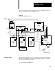
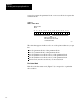
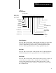
shows connections from the central ground bus to each chassis and to the
I/O chassis ground bus shown in Figure 6.17.
Figure 6.18
AC
Power and Ground Connections
Isolation
Transformer
H1H2H3H4
X1 X2
Incoming
AC
H7H4H1
X1
X2
X3
Y2Y3Y1
G
Bulletin 1388
Power
Transformer
Central
Ground Bus
L1 N
Power
Supply
for Input
Circuits
G
L1 N
Power
Supply for
I/O Chassis
Backplane
G
L1 N
G
789
11
10
9
45
G
Bulletin 1388
DC Servo
Controller
Drive
A3TB1 A2TB1
A2TB1
I/O Chassis
Ground Bus
Motor
120V AC
Fuse
120V AC
17966
+
For DAC
(Customer
Supplied)
+ Return -
15V dc
35.5V ac
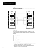
After properly installing your servo positioning assembly, formatting the
data blocks, entering the program, and integrating each axis, you start up
the system in the following sequence.
1. De-energize the CRM relay.
Startup Sequence