
Manual

Installing the Assembly
Chapter 6
614
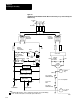
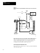
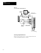
Figure 6.8
Simplified
Power Distribution with the MasterControl Relay, Loopcontactor Relay
, and
Hardware Stop
F
u
s
e
F
u
s
e
H
1
H
3
H
4
H
2
X
12
X
Isolation/
Step Down
Transformer
F
u
s
e
1
L
F
u
s
e
L
2
F
u
s
e
L
3
Incoming
AC
Disconnect
F
u
s
e
CRM
Reset
Extreme
Overtravel
Limit Switches
CRM
LCR
CRM
Use any number
of E - stop switches
in series
LCR
Backplane
Power Supply
Power Supply for
Analog Output Circuit
-15V DC
Common
+15V dc
Power Supply for
Input Circuits
H
1
H
3
H
4
H
2
Isolation/
Step Down
Transformer
Servo Drive
Dynamic
Braking
Resistor
LCR LCR
LCR
Servo
Motor
11
12
Servo Xformer
Thermal Overload
Servo Drive
Fault
Servo Motor
Thermal Overload
1771 - ES Expander
Hardware
Stop
+5 - 30V dc
Common
To Input CircuitsTo I/O Modules
CRM
CRM
CRM
+5 - 30V dc
1
NOTE:
12018
1
1
To minimize EM generation, connect a suppression network for 120V ac, AllenBradley
cat. no. 700N24; fo r220/240V ac. Electrocube part no. RG 167613 .