
Manual

Installing the Assembly
Chapter 6
69
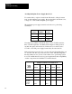
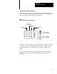
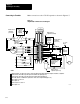
Figure 6.6
Keying Diagram for the 1771ES Expander
2
4
6
8
10
12
14
16
18
20
22
24
26
28
30
32
34
36
2
4
6
8
10
12
14
16
18
20
22
24
26
28
30
32
34
36
Keying
Bands
Upper Left Upper Right
Connector Connector
11006
Between
•
•
pins 2 and 4
pins 14 and 16
Between
•
•
pins 4 and 6
pins 32 and 34
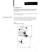
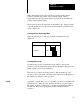
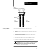
To insert a module into an I/O chassis, follow these steps:
1. Remove power from the I/O chassis before inserting or removing a
module.
2. Open the module locking latch on the I/O chassis and insert the
module into the slot keyed for it.
3. Press the module firmly to seat it into its backplane connector.
4. Secure the module in place with the module locking latch.
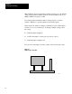
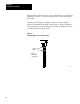
CAUTION: Do not force a module into a backplane connector;
if you cannot seat a module with firm pressure, check the
alignment and keying. Forcing a module can damage the
backplane connector or the module.
Inserting the Module