
Manual

Installing the Assembly
Chapter 6
68
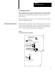
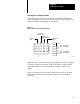
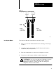
Each module is slotted at the rear edge. Position the keys on the chassis
backplane connector to correspond to these slots to allow the seating of
the module.
Insert keys into the upper backplane connectors. Position the keys
between the numbers at the right of the connectors. Refer to Figure 6.5
for the 1771-M3 controller keying position. Refer to Figure 6.6 for the
1771-ES expander keying positions.
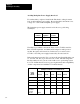
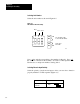
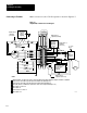
Figure 6.5
Keying
Diagram for the 1771M3 Controller
2
4
6
8
10
12
14
16
18
20
22
24
26
28
30
32
34
36
Keying
Bands
11005
Between
•
•
pins 2 and 4
pins 8 and 10