
Manual

Installing the Assembly
Chapter 6
63
Planning Module Location
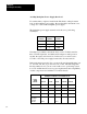
The 1771-M3 controller requires one I/O chassis slot. You can install it in
any I/O in the I/O chassis. The 1771-M3 controller uses both the output
image table byte and the input image table byte that correspond to its
location address.
The 1771-ES expander requires two slots. Install it in a pair of slots that
make up an I/O module group.
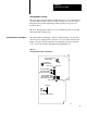
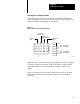
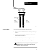
Through switches and jumpers on the 1771-ES expander, you can select
various aspects of the module’s operation. To access these switches and
jumpers, lay the 1771-ES expander on its right side and remove the left
cover. Locate the switches and jumpers through Figure 6.1.
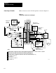
Figure 6.1
1771ES
Expander Switches and Jumpers
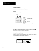
Discrete Input Resistance
Switch Assembly
Axis Number
Switch Assembly
CH A Polarity Jumper
CH B Polarity Jumper
Marker Polarity Jumper
CH A Signal Mode Jumper
CH B Signal Mode Jumper
Marker Signal Mode Jumper
Differential
Single -Ended
Marker
Logic
Jumper
Not Gated
GatedwithCHAandCHB
12013
Low -True
High - True
Setting Switches and Jumpers