
Manual

Positioning with Allen-Bradley PC
Chapter 4
44
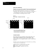
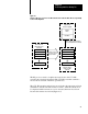
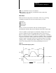
Figure 4.4
In
the 1771ES Expander, as Each Current Move is Completed, the Next Move Block is
Ready to T
ake its Place
Move 1 Move 1 Move 2 Move 3 Move 20 Move 21
Move Move 2 Move 3 Move 4 Move 21 Move
Current Move Block
Next Move Block
Time
Start
of
Move
Start
of
Move
Start
of
Move
Start
of
Move
Start
of
Move
Start
of
Move
12008
Initially, the 1771-M3 controller sends the first move block to the
1771-ES expander. Then, as each move is started the 1771-M3 controller
sequentially sends each of the remaining move blocks to the 1771-ES
expander.
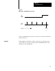
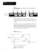
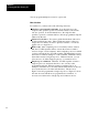
A move block for a move to position defines motion of the axis from one
position to another. Figure 4.5 shows the profile of an axis move. The
horizontal axis in the figure represents axis position. The vertical axis
represents axis velocity. Moves plotted above the position axis are in the
positive direction (from left to right), moves plotted below the position
axis are in the negative direction (right to left).
Figure 4.5
Onemove
Profile for an Axis
Rate +
Final Velocity
or Feedrate
0
Startpoint
Endpoint
Position
Acceleration
Deceleration
Constant
Velocity
Move
11010
In the move shown in Figure 4.5, the axis:
starts from a resting position
accelerates to a final velocity